Facebook
 Google
 GitHub
 Linkedin
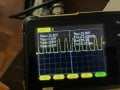
Frequency is 73.5kHz. When you say put it across the mosfet, do you mean instead of snubber going from drain to positive, go from drain to source?The inductor voltage is driven by the rate of change of the current. How fast are you switching off the transistor?? Probably very fast. Try having the snubber across the mosfet. THAT is the item that the snubber would be used to protect.
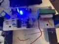
PWM For High Frequency Transformer
- Thread starter rwfwef
- Start date