High Frequency Transformer Driving Circuit Issue

Thread Starter

rwfwef

Joined Sep 14, 2025
68
Hi there,

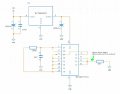
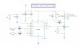
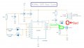
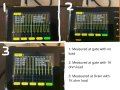
I made a PWM and there is an issue thats happening on my MOSFET output. I've checked my gate signal and the wave form looks normal, and even with a load on the MOSFET drain, the circuit still runs fine. The moment I probe my drain on the MOSFET, thats where things go wrong. The signal going into my gate is 91KHz at 50% duty cycle which is what I want. My drain however is running at 102KHz at 75% duty cycle. Any idea what's causing this issue? Btw in the circuit, I have the Primary coil replaced with a 1K ohm resistor just to have the MOSFET under a bit of load.
 

Attachments

ericgibbs

Joined Jan 29, 2010
21,390
hi rw,
Consider the possibility that the Drain signal is showing the correct frequency of 102kHz of the 4093 oscillator.

And when you measure the Gate frequency signal, the capacitive loading effect of the Probe is causing the frequency to be reduced to 91kHz

E
 

Thread Starter

rwfwef

Joined Sep 14, 2025
68
hi rw,
How accurate and stable do you require the 91kHz to be?

Can you say why you are using 91kHz?

E
Realistically it doesnt need to be 91KHz specifically, but somewhere around there as the transformer needs the high frequency do to low primary inductance, and I cant go too high because then skin effect. A range I would be happy with for the frequency can be from 88-94KHz at around 50% duty cycle.

As for stability, I'm not looking for perfection but if there is something that's a bit better than the 4093 and it's not too expensive, please let me know. Currently I'm planning on swapping the 4093 with SN74AHCT132N, just waiting for it to arrive. Is that any better?
 

panic mode

Joined Oct 10, 2011
4,864
no...oscillator is ok as confirmed by scope. i would just get rid of the diode connected to mosfet drain, replace it by a jumper. you will get 50% duty cycle output.
 
Last edited:

panic mode

Joined Oct 10, 2011
4,864
about snubber values, i would pick low value resistor and higher value cap.
10k is high so transistor will see high voltage spikes. but you do not want to exceed 600V that your mosfet is rated for.
 

panic mode

Joined Oct 10, 2011
4,864
you can leave diode in place, just short it.

i think you will see better results if the snubber resistor value is low.
capacitor value should be larger, say 220nF-470nF and rated for voltage that will be exposed to.
simple ways to get reasonably close is to match impedances of inductor and capacitor or use simulator like LTSpice
Xl=Xc
2*pi*f*L = 1/(2*pi*f*C)
C=1/(4*pi*pi*f*f*L)

that way they would form a resonant circuit and everything else is known
f = 91kHz
pi=3.14
L = 7uH

resistor is there to dampen the oscillations (transformer load is doing the same thing).
too low R value and you get resonance with high current.
too large R value and C has no effect... inductor energy is absorbed by load or dissipated by insulation breakdown - somewhere... (hopefully not mosfet or capacitor)

The simulator is LTspice (formerly switcherCad). it is free software so everyone should have it
 
Last edited:

Thread Starter

rwfwef

Joined Sep 14, 2025
68
you can leave diode in place, just short it.

i think you will see better results if the snubber resistor value is low.
capacitor value should be larger, say 220nF-470nF and rated for voltage that will be exposed to.
simple ways to get reasonably close is to match impedances of inductor and capacitor or use simulator like LTSpice
Xl=Xc
2*pi*f*L = 1/(2*pi*f*C)
C=1/(4*pi*pi*f*f*L)

that way they would form a resonant circuit and everything else is known
f = 91kHz
pi=3.14
L = 7uH

resistor is there to dampen the oscillations (transformer load is doing the same thing).
too low R value and you get resonance with high current.
too large R value and C has no effect... inductor energy is absorbed by load or dissipated by insulation breakdown - somewhere... (hopefully not mosfet or capacitor)

The simulator is LTspice (formerly switcherCad). it is free software so everyone should have it
wouldnt using an LC circuit cause the circuit to go from square wave to more of a sine wave?
 

panic mode

Joined Oct 10, 2011
4,864
yes... but with 10k, that is not visible.
keep in mind that voltage across inductor can change suddenly but not the current.
(and voltage across capacitor cannot change instantly but current can).

bypass diode, put 470nF as capacitor and reduce resistor to 10-22 Ohm and you will see something that resembles sine halfwave
 

Thread Starter

rwfwef

Joined Sep 14, 2025
68
yes... but with 10k, that is not visible.
keep in mind that voltage across inductor can change suddenly but not the current.
(and voltage across capacitor cannot change instantly but current can).

bypass diode, put 470nF as capacitor and reduce resistor to 10-22 Ohm and you will see something that resembles sine halfwave
The goal is to try and keep the square wave at the moment. Anyway I'm planning on putting the resistor and capacitor in parallel instead of in series because based on other LCD snubbers it's in parallel rather than in series.

I've run into a new issue now. I swapped my CD4093 for an SN74AHCT132N as the specs for that seemed better and was hoping that the circuit would have less jitter at the output but now the circuit doesnt work at all with that part. I checked the manufactures datasheet to adjust connections to the correct pins, added a 7805 (part is made for 5Vin) and yet it still won't output anything. Vout is close to 0V. Can the SN74AHCT132N not be used as a square wave oscillator?
 

MisterBill2

Joined Jan 23, 2018
27,159
IF the operation of the circuit changes when you probe the drain connection, then MY conclusion is that your scope probing is affecting the circuit. That happens frequently if the incorrect type of probe is used. I have seen it happen many times, mostly to those folks unfamiliar with scope probe use.
 

Thread Starter

rwfwef

Joined Sep 14, 2025
68
IF the operation of the circuit changes when you probe the drain connection, then MY conclusion is that your scope probing is affecting the circuit. That happens frequently if the incorrect type of probe is used. I have seen it happen many times, mostly to those folks unfamiliar with scope probe use.
That could be the issue, I have a different probe so maybe I'll try that. Thx
 

Thread Starter

rwfwef

Joined Sep 14, 2025
68
So I'm considering going back to the first circuit I had posted (I'll put it in this post attachment), but with some changes compared to the first. Is there a better chip than the CD4093 to use in this circuit configuration? Overall it's not bad but I would like the circuit to be more stable in the sense that the frequency and duty cycle bounce around.

Or is there a much better circuit for this application (High Frequency Square Wave Generator to drive MOSFET)

Already tried 555 timer circuits, TL494 circuit (wasn't able to get it to work properly), 4093, SN74AHCT132N circuit (wasn't able to get it to work properly)
 

Attachments

Top