PWM For High Frequency Transformer

Thread Starter

rwfwef

Joined Sep 14, 2025
68
Hi there,

I have currently built a few different types of PWM's for a high frequency transformer but all of them seem to have a jitter problem. I'm not looking for perfection but something that's going to send out a decently smooth and stable square wave without jitter.

I'm not looking for an adjustable PWM in the sense that I can adjust it with POT's, I'm looking to make one and set it to whatever frequency I desire (In my case something between 88KHz-92KHz) and also 50% duty cycle.

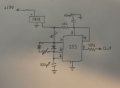
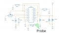
I've tried 555 timer circuits, I've tried 2 different types of NAND Schmitt Trigger circuits and so far nothing has satisfied.

What is the best approach to building a decently stable PWM?
 

schmitt trigger

Joined Jul 12, 2010
2,027
Once again;
Look at the 3524 block diagram so you understand how you can create a variable square PWM wave from a triangle wave.
EDIT: actually a sawtooth wave.
 

Thread Starter

rwfwef

Joined Sep 14, 2025
68
What to you is "decently stable"?
How much jitter can you tolerate?
Post the exact schematic of the 555 timer you have tried.

This is pretty close to how it was. Cant remember the POT values. Other than this I'm pretty sure I tried the version without the diodes and just had a single resistor between pin 7 and pin 6 and then the rest pretty much the same except for values and I was using 12V power supply so no need for voltage reg like in this one.

As for jitter tolerance and stability, I don't know what measurement to use for that. On my oscilloscope the frequency and duty cycle bounce around a bit and there is noticeable jitter when actually looking at the output graph. I guess what I want is something that wont cause my frequency and duty cycle to bounce around as much. Eg right now my duty cycle goes from 48% to 53% give or take when it bounces. If it can be more stable at around 49%-51% or less. As for frequency I cant remember how much that was bouncing maybe more than 500Hz at 90KHz +.
 

Attachments

Last edited:

Papabravo

Joined Feb 24, 2006
22,058
Looking for a square wave one specifically but thx.
It is a square wave one. The output of the comparator is a SQUARE WAVE. The other input sets the PWM reference level. This works for either fixed or variable PWM, although I'm not sure how useful a fixed PWM would be
 

Thread Starter

rwfwef

Joined Sep 14, 2025
68
It is a square wave one. The output of the comparator is a SQUARE WAVE. The other input sets the PWM reference level. This works for either fixed or variable PWM, although I'm not sure how useful a fixed PWM would be
Yes, I realized as I saw the datasheet that it also showed a square wave. I don't want to have potentiometers in the circuit or at least the final circuit. I can't say that they help the circuit run smooth. In my experience, just by placing my finger it, even without adjusting the knob, it has caused the output to change until I remove my finger.
 

Thread Starter

rwfwef

Joined Sep 14, 2025
68
A 100nF capacitor from the 555 pin 5 to ground should reduce the jitter.

Your jitter values and change in frequency seem very high.
What oscilloscope were you using?
This is my oscilloscope

And ok, about 150nF pin 5 to ground.

I wanted to avoid the 555 as I've heard that it's not the best. I'm not looking for anything crazy expensive or complex, but something that will be smoother and more consistent than the 555. Whether it's other IC's or whatever
 

MisterBill2

Joined Jan 23, 2018
27,159
You can also create a PWM signal using exclusively digital means, and not even a processor module. The down-side is that the duty cycle is not continuously variable, but rather in steps, such as one percent steps from zero to 100%, with a rock-solid frequency. The scheme is to use a digital counter and a crystal oscillator. The pulse goes "high" at the count reset to zero, and then switches to "low" when the counter passes the preset count. Not that complex unless you want to be constantly changing the duty cycle with a variable voltage. AND certainly you can do exactly the same thing with a little processor module. With no jitter and a more convenient setting scheme.
 

Thread Starter

rwfwef

Joined Sep 14, 2025
68
So I ended up taking the route of using a GL494 circuit as I already had the parts to make this circuit and didn't want to look at buying other things especially if this circuit can work well. Below in attachments I have the circuit diagram I used and here is a video to show my oscilloscope output reading. Is there a way to reduce/ eliminate the output from bouncing like it does in the video? I assume swapping the potentiometer for the correct value resistors would help smoothen the circuit a bit more, but I'm pretty sure I won't fix the entire issue.

Any suggestions on what to add, replace, or swap on the circuit? Would the TL494 or another similar chip be better?
 

Attachments

MisterBill2

Joined Jan 23, 2018
27,159
So I ended up taking the route of using a GL494 circuit as I already had the parts to make this circuit and didn't want to look at buying other things especially if this circuit can work well. Below in attachments I have the circuit diagram I used and here is a video to show my oscilloscope output reading. Is there a way to reduce/ eliminate the output from bouncing like it does in the video? I assume swapping the potentiometer for the correct value resistors would help smoothen the circuit a bit more, but I'm pretty sure I won't fix the entire issue.

Any suggestions on what to add, replace, or swap on the circuit? Would the TL494 or another similar chip be better?
I am hoping that your scope vertical input is the voltage across that 470 ohm resistor.
 

Thread Starter

rwfwef

Joined Sep 14, 2025
68
OK, so what part if the signal is bouncing around??If you trigger on the rising edge half way up that should b OK.
you see how the sqaure wave moves back and forward on the oscilloscope and the duty cycle and frequency arent able to hold at a stable point?

That's what I'm trying to fix. Make everything more stable.

Also what do you mean by trigger rising edge halfway up?
 

MisterBill2

Joined Jan 23, 2018
27,159
OK, Now I see what should be added to the circuit shown with post #6.
You first need the 0.1 MFD capacitors next to the 12 volt voltage regulator IC! That is a part of the basic application notes. AND, in addition, an additional capacitor, 47MFD or a bit more, near the 7812 IC regulator circuit, directly across the 12 volts supply, to stabilize the supply voltage. Any noise on the supply would be a cause for the variations that you see. Any variation in the supply will certainly affect what you see on the scope, even if it does not affect the actual signal. And it is not totally clear to me if it is actually upsetting the signal or only the scope display. But the caps are should solve the problem in either case.
 

Thread Starter

rwfwef

Joined Sep 14, 2025
68
OK, Now I see what should be added to the circuit shown with post #6.
You first need the 0.1 MFD capacitors next to the 12 volt voltage regulator IC! That is a part of the basic application notes. AND, in addition, an additional capacitor, 47MFD or a bit more, near the 7812 IC regulator circuit, directly across the 12 volts supply, to stabilize the supply voltage. Any noise on the supply would be a cause for the variations that you see. Any variation in the supply will certainly affect what you see on the scope, even if it does not affect the actual signal. And it is not totally clear to me if it is actually upsetting the signal or only the scope display. But the caps are should solve the problem in either case.
Right now the circuit I’m using is the circuit I have posted most recently (post #12 attachments). I’m not using the 7812, nor the MOSFET, nor any of the Snubber stuff. The circuit ends at the 470 ohm resistor where I was measuring and the power supply is literally a 12V power supply. Right now I figure it would be best to first fix the PWM before running through the rest of the circuit so I know that it’s not something else causing this problem.

Is it possible then that the bouncing around is my scope and not the circuit?

Also I tried a different type of 494 maybe it was a DL494 and I’m pretty sure the bouncing got worse with it…
 

Justloadit

Joined Sep 17, 2024
14
I have currently built a few different types of PWM's for a high frequency transformer but all of them seem to have a jitter problem. I'm not looking for perfection but something that's going to send out a decently smooth and stable square wave without jitter.
Could you clarify the intended application?
Simply stating "High Frequency Transformer" doesn’t provide enough context. Based on your mention of a 50% duty cycle, I’m assuming you're working on a step-up or step-down power supply using a push-pull topology.
There’s generally no issue with minor shifts in the switching period—as long as the shift is symmetrical across both halves of the cycle. If not, you risk incomplete demagnetization of the transformer core, which can lead to saturation and inefficiency and FET heating up due to shoot through.

Another critical factor is how you manage dead time during zero-voltage switching transition. Your driver circuit must be capable of switching the FETs on and off extremely quickly. The FETs themselves should support fast transitions—ideally in the range of 60 to 90 nanoseconds. 90KHz is approximately 11milliseconds or 5.5mSecs per half cycle, a dead time of 3 or 4 mSecs is a considerable amount of time taken off your 50% expected switch time. Check the datasheet for diode characteristics across the FET junction to confirm this. My experience even with very fast switching silicon FETs is around 3mSecs, with good transformer design, and complete discharge of the magnetic core of the transformer. Maybe slow down the switching, there is no advantage going so high, it makes the design more critical, even to the extent of the PCB traces, and where FET position in relation to the transformer and to each other becomes critical too. Consider going down to frequencies between 20 and 40KHz. There are many iron cores available at these frequencies, the higher frequencies require what I call exotic cores with Litz wire and other design issues to make it work successfully.

At the operating frequencies you're targeting, slow-switching FETs will distort your duty cycle. Instead of a clean 50%, you may end up with only 20–30% usable conduction time, with the remainder lost to dead time and transition delays.

Also, relying on pull-up or pull-down resistors for switching is insufficient. They lack the drive strength needed to turn off the FETs rapidly, forcing you to extend dead time and further reducing the effective power transfer window through the transformer.
Lastly, your oscilloscope’s 200kHz bandwidth is inadequate for analyzing high-speed switching wave forms in power electronics. You’ll need a minimum 2 channel scope with at least 100MHz bandwidth to accurately capture rise/fall times and validate your switching behavior. Low-bandwidth scopes will miss critical transitions and won’t support reliable circuit design.

Once I know what your application is I can make a few more suggestions.
 

MisterBill2

Joined Jan 23, 2018
27,159
Consider that everything that influences the voltage at the vertical input of the scope trigger and the vertical position of the display.
Is the circuit built up on one of those experimenter plug-in breadboards? Sometimes there are poor connections in those setups. AND there might possibly be a problem with the scope "common " side connection. If the input shield was connected to the grounded side of the 470 ohm resistor that would be the best place.
One more possible thing could be the scope sweep trigger setting. Maybe.
One more thing is that without the FET switches in the circuit I really doubt that they are having much effect on anything at all.
 
Top