PWM For High Frequency Transformer

Thread Starter

rwfwef

Joined Sep 14, 2025
68
Consider that everything that influences the voltage at the vertical input of the scope trigger and the vertical position of the display.
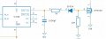
Is the circuit built up on one of those experimenter plug-in breadboards? Sometimes there are poor connections in those setups. AND there might possibly be a problem with the scope "common " side connection. If the input shield was connected to the grounded side of the 470 ohm resistor that would be the best place.
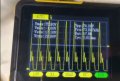
One more possible thing could be the scope sweep trigger setting. Maybe.
One more thing is that without the FET switches in the circuit I really doubt that they are having much effect on anything at all.
I am using a plugin breadboard. For the build I plan on soldering but I didnt want to solder as that limits quick changing of parts. But yah I'm sure soldering will help make it more stable. I was also thinking of adding a MOSFET driver as suggested, just haven't been able to get one yet. But I'm thinking of getting something like the TC4420, TC4426, or TC4427
 

Thread Starter

rwfwef

Joined Sep 14, 2025
68
Could you clarify the intended application?
Simply stating "High Frequency Transformer" doesn’t provide enough context. Based on your mention of a 50% duty cycle, I’m assuming you're working on a step-up or step-down power supply using a push-pull topology.
There’s generally no issue with minor shifts in the switching period—as long as the shift is symmetrical across both halves of the cycle. If not, you risk incomplete demagnetization of the transformer core, which can lead to saturation and inefficiency and FET heating up due to shoot through.

Another critical factor is how you manage dead time during zero-voltage switching transition. Your driver circuit must be capable of switching the FETs on and off extremely quickly. The FETs themselves should support fast transitions—ideally in the range of 60 to 90 nanoseconds. 90KHz is approximately 11milliseconds or 5.5mSecs per half cycle, a dead time of 3 or 4 mSecs is a considerable amount of time taken off your 50% expected switch time. Check the datasheet for diode characteristics across the FET junction to confirm this. My experience even with very fast switching silicon FETs is around 3mSecs, with good transformer design, and complete discharge of the magnetic core of the transformer. Maybe slow down the switching, there is no advantage going so high, it makes the design more critical, even to the extent of the PCB traces, and where FET position in relation to the transformer and to each other becomes critical too. Consider going down to frequencies between 20 and 40KHz. There are many iron cores available at these frequencies, the higher frequencies require what I call exotic cores with Litz wire and other design issues to make it work successfully.

At the operating frequencies you're targeting, slow-switching FETs will distort your duty cycle. Instead of a clean 50%, you may end up with only 20–30% usable conduction time, with the remainder lost to dead time and transition delays.

Also, relying on pull-up or pull-down resistors for switching is insufficient. They lack the drive strength needed to turn off the FETs rapidly, forcing you to extend dead time and further reducing the effective power transfer window through the transformer.
Lastly, your oscilloscope’s 200kHz bandwidth is inadequate for analyzing high-speed switching wave forms in power electronics. You’ll need a minimum 2 channel scope with at least 100MHz bandwidth to accurately capture rise/fall times and validate your switching behavior. Low-bandwidth scopes will miss critical transitions and won’t support reliable circuit design.

Once I know what your application is I can make a few more suggestions.
This is to make a high voltage, high frequency power supply (70W max), kinda like a neon sign driver.

For this transformer I'm using a pulsing square wave to drive a single MOSFET.

The MOSFET diode has a recovery time of 240ns. Here's the datasheet in case you want to take a quick look. Maybe you'll see something that I missed or am not aware of? Switch time, rise time, etc is at end of page 4 and beginning of page 5.

I was also planning on adding a MOSFET driver to the circuit, thinking of using TC4420, TC4426, or TC4427.

Also one issue I was having in the past is that even if the MOSFET gate was getting 50% duty cycle at around 90kHz (I can't remember the exact frequency), the duty cycle on the drain pin was 75% and the frequency was over 10kHz higher compared to gate.

In terms of core, I'm using ferrite 77. Can it not be used at 90kHz?
 
Last edited:

Justloadit

Joined Sep 17, 2024
14
This is to make a high voltage, high frequency power supply (70W max), kinda like a neon sign driver.

For this transformer I'm using a pulsing square wave to drive a single MOSFET.

The MOSFET diode has a recovery time of 240ns. Here's the datasheet in case you want to take a quick look. Maybe you'll see something that I missed or am not aware of? Switch time, rise time, etc is at end of page 4 and beginning of page 5.

I was also planning on adding a MOSFET driver to the circuit, thinking of using TC4420, TC4426, or TC4427.
70W is a fair sized SMPS, if you start off with 12V, you need just over 5A to drive the primary side. Data sheet for the FET chosen, at best will have an RDS of 180 milli ohms. Using Ohms law I^2 x R, at best will create just under 5W of heat when switched on, but if 50% duty then about 2.5W since it is on for half the time. Taking switching loses and other issues at the high frequency you wish to run at, will increase to about 4W. This is a fair amount of heat to get rid off. Whilst a heat sink will take care of this, maybe consider another FET, such as IRF3315, which has a RDS=70milli ohm, using the same source voltage, will yield a theoretical power of 1.7W, but at 50% duty cycle then approximately 0.9W, now with switching loses you could expect 1.2W or so. Reducing the switching frequency will reduce the switching loses. There is heat generated every time the FET switches on and off. So lower frequency less heat generated.

Now since you are only using half cycle, there is no need to be concerned with exactly 50% duty cycle, what is important, is that the transformer magnetization is reduced to zero during the off cycle. The jittering will have no effect on your circuit for this application.

Not sure what your budget is, but look at this FET as well IRF3415 , much better RDS
Also one issue I was having in the past is that even if the MOSFET gate was getting 50% duty cycle at around 90kHz (I can't remember the exact frequency), the duty cycle on the drain pin was 75% and the frequency was over 10kHz higher compared to gate.
What you were seeing, is the delayed reaction of the gate charging up to switch the FET on, (**running in linear range) and at the higher frequencies, there is less ON time hence the reason to use gate drivers, to ensure there is sufficient current available to charge and discharge the FET gate. Switching on and off too fast also has its implications. Using the driver specifications for switch on current, and switch off current, you can calculate the gate resistance for the gate voltage used. You will note that the switch on current is lower than the switch off current. So how to get the advantage of the higher current on switch off? Use a signal diode in reverse with the respective resistor for the switch off current. You will see many circuits with this diode implemented. By changing the gate resistor you can reduce ringing but still get fast switching.

**Slow switching of the gate will cause the FET to work in its linear range where the RDS is not as per specification, which means that during this time, there is heat generated by the RDS being ohms not milli ohms.

In terms of core, I'm using ferrite 77. Can it not be used at 90kHz?
This core is rated to 100KHz. The issue here is the semiconductors required to run this high frequency. In this application not necessary at all, unless physical size is an issue, the the extra expense and design parameters would not be an issue. The other issue you need to look at is what is called Skin Effect, and may require the use of Litz wire to reduce this problem. Do some research on skin effect on electrical wire.
 

Thread Starter

rwfwef

Joined Sep 14, 2025
68
70W is a fair sized SMPS, if you start off with 12V, you need just over 5A to drive the primary side. Data sheet for the FET chosen, at best will have an RDS of 180 milli ohms. Using Ohms law I^2 x R, at best will create just under 5W of heat when switched on, but if 50% duty then about 2.5W since it is on for half the time. Taking switching loses and other issues at the high frequency you wish to run at, will increase to about 4W. This is a fair amount of heat to get rid off. Whilst a heat sink will take care of this, maybe consider another FET, such as IRF3315, which has a RDS=70milli ohm, using the same source voltage, will yield a theoretical power of 1.7W, but at 50% duty cycle then approximately 0.9W, now with switching loses you could expect 1.2W or so. Reducing the switching frequency will reduce the switching loses. There is heat generated every time the FET switches on and off. So lower frequency less heat generated.

Now since you are only using half cycle, there is no need to be concerned with exactly 50% duty cycle, what is important, is that the transformer magnetization is reduced to zero during the off cycle. The jittering will have no effect on your circuit for this application.

Not sure what your budget is, but look at this FET as well IRF3415 , much better RDS

What you were seeing, is the delayed reaction of the gate charging up to switch the FET on, (**running in linear range) and at the higher frequencies, there is less ON time hence the reason to use gate drivers, to ensure there is sufficient current available to charge and discharge the FET gate. Switching on and off too fast also has its implications. Using the driver specifications for switch on current, and switch off current, you can calculate the gate resistance for the gate voltage used. You will note that the switch on current is lower than the switch off current. So how to get the advantage of the higher current on switch off? Use a signal diode in reverse with the respective resistor for the switch off current. You will see many circuits with this diode implemented. By changing the gate resistor you can reduce ringing but still get fast switching.

**Slow switching of the gate will cause the FET to work in its linear range where the RDS is not as per specification, which means that during this time, there is heat generated by the RDS being ohms not milli ohms.


This core is rated to 100KHz. The issue here is the semiconductors required to run this high frequency. In this application not necessary at all, unless physical size is an issue, the the extra expense and design parameters would not be an issue. The other issue you need to look at is what is called Skin Effect, and may require the use of Litz wire to reduce this problem. Do some research on skin effect on electrical wire.
wow, lot's of info there, thx.

I'm using 12V to test just to limit parts on the board and to make sure the PWM works well. The final circuit might range from 12V-25V and then I'll put in a voltage regulator for the IC's if they need it.

That MOSFET is within the budget so I'm considering getting one. Thx for the suggestion. Just gotta find a local place that has them because shipping alone is going to cost more than buying 10 of them online.

Currently looking at also getting gate driver. Would you recommend 1N4148 for signal diode?

I took into account for skin effect. The largest I use is 26AWG. It can handle 107kHz so no problems there.
 

MisterBill2

Joined Jan 23, 2018
27,571
For now, one suggestion is to clip the scope input ground side directly to the grounded lead of that 470 ohm resistor, and clip the signal side directly to the other lead of that resistor. And experiment with the sweep trigger level adjustments. In case it is a wek signal or a noisy ground connection.
 

Justloadit

Joined Sep 17, 2024
14
Currently looking at also getting gate driver. Would you recommend 1N4148 for signal diode?

I took into account for skin effect. The largest I use is 26AWG. It can handle 107kHz so no problems there.
Yes 1N4148 is accepted and widely used in industry.

With respect to skin effect, it is not always about increasing the diameter of the wire, what may occur is that you run out of bobbin space for the turns you require. One trick is to get the thinnest wire and use a number of strands together to make up the amount of copper you need for the current, make up a multi strand when winding.

Have you inquired at Digi-key or Mouser for your components?
 

Thread Starter

rwfwef

Joined Sep 14, 2025
68
Yes 1N4148 is accepted and widely used in industry.

With respect to skin effect, it is not always about increasing the diameter of the wire, what may occur is that you run out of bobbin space for the turns you require. One trick is to get the thinnest wire and use a number of strands together to make up the amount of copper you need for the current, make up a multi strand when winding.

Have you inquired at Digi-key or Mouser for your components?
I use multiple stands of 26AWG for the primary to ensure I have space to wind to get over x125 voltage input multiplication. But I don’t twist them together as that adds thickness. Instead I stack them.

I use digikey normally for online. Haven’t used Mouser. DigiKey has a flat shipping rate of $20 unless order is over $100 if I’m not mistaken.

Also is there a good alternative for the IRF3415 that's popular? I haven't found any in store.
 
Last edited:

Justloadit

Joined Sep 17, 2024
14
Try https://us.rs-online.com they may have alternatives. They also have a search facility, a bit cumbersome. Look for products, maybe not in this order, I used it a while ago and can not quite remember - semiconductors discreet, power MOSFET or FETs then using filters you can select voltage, package and other specifications to narrow down what is in stock.
 

Thread Starter

rwfwef

Joined Sep 14, 2025
68
Yes IRFP250 will work. Since you are using 12 to 25V you could also look at IRFZ44R, lower voltage device but other specs are good.
1N914 will also work.
I’ll see if I can get that IRFZ44R at my local store.

Would the IRFP252 be another option? I saw it has a much higher current rating.
 

Justloadit

Joined Sep 17, 2024
14
I’ll see if I can get that IRFZ44R at my local store.

Would the IRFP252 be another option? I saw it has a much higher current rating.
Yes IRFP525 is another option, off course it is a TO-247 package, where as the other devices are TO-220.

Never worry about the maximum current a FET can operate at, yes this is crucial when designing to ensure that you have a device that can handle the required current. What is important, is that the device selected as a rule of thumb is the operating voltage of the FET is at least twice the circuit voltage. This becomes crucial in push/pull circuits. My criteria is always the amount of heat that the junction generates during operation. The less heat required to dissipate under operation the better as long as the device cost is acceptable for the operation. Adding a larger heat sink and fans may do the task of cooling the device, but in the long run this is extra cost and prone to mechanical failure of the fan, and noisy.
 

Thread Starter

rwfwef

Joined Sep 14, 2025
68
Circuit works!

I put a load where the primary coil would be and put probe near drain pin and it worked well. 88KHz at around 50% duty cycle. Couldn't test with coil because I haven't wound one yet, but hopefully all will go well.

The TL4426 worked similarly to the TC4426 (might be the same just different label). I also plan on swapping the UF4007 with an STTH5L06RL as that can handle more current. I also am able to run higher voltage now. I swapped out capacitors for ones that have higher voltage rating (50V minimum rating on +12V-30V side)

I'll post the circuit diagram in attachments in case you or anyone else wants to take a look and see if there's anything wrong.

Thx again for all the help! What a difference!
 

Attachments

Last edited:

Thread Starter

rwfwef

Joined Sep 14, 2025
68
Thinking of going back to 20V max. Realized that even though the circuit can take 30V, the transformer flux is going to be higher then I would want it. Don't want to saturate the core. So if I go back, the 2 470uF capacitors at the Vin would be replaced with 1000uF cap.
 

Justloadit

Joined Sep 17, 2024
14
Since you are not running the load right now, you will not notice the effect of the gate resistor that you have selected. I think that the 470 ohm resistor in series with the FET may be too high, and cause the FET to start in the linear range operation of the FET, causing the junction to heat. I suggest to get a value between 47 ohms and not more than 100 ohms. Place a 47 ohms resistor in series with the 1N914 diode, to reduce the current in the gate when the FET is switched off. Just remember that this resistor will always be in parallel with the resistor used for the on state of the gate, and must be accounted for when calculating the maximum current that the driver can accommodate. Once you have your transformer sorted out, change the frequency to 60KHz and you will notice no performance change in the output, but you will notice that the FET will run cooler. Just remember that diodes have a transition time from when they forward conduct to when they block the reverse flow. For a brief period they reverse conduct due to the capacitance effect of the junction. This is referred to as Reverse Recovery Time or trr. In the diode you selected, STTH5L06RL it is between 65nS and 95nS is a good choice, this is the typical average you are going to get from Schottky Diodes. This becomes more pronounced when you delve into push/pull designs and higher current flows in the transformer secondary.
 

MisterBill2

Joined Jan 23, 2018
27,571
"Reverse Recovery Time" is one of those details that certainly can be inconvenient. It first caused me a problem when I replaced a rectifier tube with diodes, in a small tube amplifier circuit in a radio. Suddenly there were tiny 120 Hz spikes on the DC power bus to the output stage. It took using an oscilloscope with a high gain and AC coupling to even see the problem, because it was not in the audio signal path, but only on the DC line. The fix was adding 0.01mfd capacitors on the DC power bus.
 

Thread Starter

rwfwef

Joined Sep 14, 2025
68
Since you are not running the load right now, you will not notice the effect of the gate resistor that you have selected. I think that the 470 ohm resistor in series with the FET may be too high, and cause the FET to start in the linear range operation of the FET, causing the junction to heat. I suggest to get a value between 47 ohms and not more than 100 ohms. Place a 47 ohms resistor in series with the 1N914 diode, to reduce the current in the gate when the FET is switched off. Just remember that this resistor will always be in parallel with the resistor used for the on state of the gate, and must be accounted for when calculating the maximum current that the driver can accommodate. Once you have your transformer sorted out, change the frequency to 60KHz and you will notice no performance change in the output, but you will notice that the FET will run cooler. Just remember that diodes have a transition time from when they forward conduct to when they block the reverse flow. For a brief period they reverse conduct due to the capacitance effect of the junction. This is referred to as Reverse Recovery Time or trr. In the diode you selected, STTH5L06RL it is between 65nS and 95nS is a good choice, this is the typical average you are going to get from Schottky Diodes. This becomes more pronounced when you delve into push/pull designs and higher current flows in the transformer secondary.
Here's the new diagram with a 50ohm resistor and 1N914 in series with that resistor. Is this what you meant?

Is lower frequency better in general? Like if I went lower than 60KHz, would that be better for the MOSFET? I am planning on putting a big heat sink on the MOSFET. Also I can't lower the frequency too much either, because I would then have to put more primary turns otherwise Bmax would get higher and I don't want to be near the core saturation limit. I also dont want to add more primary turns because the turns ratio is over 1:100 so adding 1 more turns requires alot more secondary turns. Anyway I'm thinking of lowering the frequency, maybe closer to 72KHz.
 

Attachments

Last edited:

Thread Starter

rwfwef

Joined Sep 14, 2025
68
So a new problem has occurred now. Driving circuit works fine but when I hooked up my primary coil, I got massive voltage overshooting. My Vin is 19V and I'm getting over 75V spikes at the drain pin. Circuit and oscilloscope reading in attachments.

Please note I currently have no secondary coil wound, just my primary, so right now primary coil is just an inductor.

Would this be caused because of my snubber circuit having incorrect values?

Circuit Correction: Snubber circuit diode is not UF4007, it is STTH5L06RL
 

Attachments

MisterBill2

Joined Jan 23, 2018
27,571
The inductor voltage is driven by the rate of change of the current. How fast are you switching off the transistor?? Probably very fast. Try having the snubber across the mosfet. THAT is the item that the snubber would be used to protect.
 
Top