Push buttons on Trio CS-2070 Oscilloscope are not responding and some constantly engaged

Thread Starter

Tp86

Joined Sep 13, 2023
216
How many digits is your multimeter?
4 digits

First thing is to give that PCB a good clean to ensure no corrosion or dirt is shorting /CONT high. Next is to examine it closely to check for any cracks, or broken vias.
I used isopropel alcohol with a brush and cleaned it a few times on both sides. It seems to have no difference. I cant seem to see any damage at all. It all looks quiet good. I'll have another look.

I would unsolder IC8 and install an IC socket in its place.
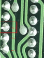
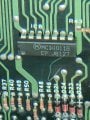
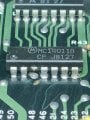
I tried to unsolder pin 3 of IC8 to see if it would work but i notice the throughhole's in which the ic pins go through seem to be of almost the same diameter so I cant insulate the pin 3 without cutting it off. If I put in a socket, will there be enough room for it to physically fit due to the very small diameter throughholes? (I've attached a picture of what I did. I used an electric solderer pump and then some solder wick)

I suppose I should order a new IC8 to test if it is the real fault as we are running out of ways to isolate it?
 

Attachments

MrChips

Joined Oct 2, 2009
35,276
No, we have not run out of ways to test this.
Don’t give up so quickly. We still have more tests to conduct.

Go ahead and unsolder IC8. It would be nice to remove it still intact. Then we can test it on a breadboard. If this proves to be difficult, snip the IC package from the leads and unsolder the leads one at a time.

The cost of IC is minimal.
 

Irving

Joined Jan 30, 2016
5,195
I'd cut pin 3 on the front of the board as close to the PCB as possible then unsolder and remove the bit in the hole. Once isolated it will be much easier to find the culprit.

Later you can fix the break with an offcut from a passive component.

You could order a replacement but I'd wait until we've finish testing in case there's something else to be ordered.

While you could remove IC8 completely my preference on older PCBs is to do as little as possible at first.
 

Irving

Joined Jan 30, 2016
5,195
In the meantime you could try disconnecting P6 and grounding the /CONT line with, say, a 1k resistor, or some similar low value. If /CONT goes to an acceptably low level then it's a reasonable bet that the pull down output MOSFET in IC8a has failed and the high level we see is just open inputs. On the other hand, if it drops to a lower voltage, but not a '0' then it's being actively driven high by IC8a which suggests a failed part, or an input on another device has failed, or there is a low impedance short to +VM.
 

Thread Starter

Tp86

Joined Sep 13, 2023
216
In the meantime you could try disconnecting P6 and grounding the /CONT line with, say, a 1k resistor, or some similar low value. If /CONT goes to an acceptably low level then it's a reasonable bet that the pull down output MOSFET in IC8a has failed and the high level we see is just open inputs. On the other hand, if it drops to a lower voltage, but not a '0' then it's being actively driven high by IC8a which suggests a failed part, or an input on another device has failed, or there is a low impedance short to +VM.
Interesting. It seems to have an actively fed as I shorted /CONT to GND through 2K resister and /CONT reads 2.8VDC. By the way we are just trying to eliminate a phantom voltage from a capacitance coupling with very low charge here right?

Should I still cut pin 3 anyway or have we ruled out IC8 is okay?
 

Irving

Joined Jan 30, 2016
5,195
Well 2.8v across 2k = 1.4mA and the spec for a mc14011 @25degC suggests an output impedance of around 500 - 1k on 5v supply so that does seem to suggest its actively being pulled up, which would suggest IC8 is faulty. The only way to definitively be sure is to isolate that pin. This doesn't look like a phantom voltage. The inputs of the other connected chips should only source/sink 15uA and I don't see any pull-up resistors, so in the absence of any internal physical short (its possible an input gate has gone 'soft') that's still my initial hypothesis.

Do the other three gates in that IC8 appear to be working correctly?
 

MrChips

Joined Oct 2, 2009
35,276
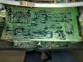
You have three ways of isolating IC8-3 on X77-1130-01 board.

1) Snip pin-3 from above as @Irving suggested.
2) Cut the track from IC8-3 to IC5-1 on the component side.
3) Unsolder IC8 completely from the board, which is what you will have to do if it turns out IC8 is faulty.
 

Thread Starter

Tp86

Joined Sep 13, 2023
216
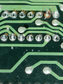
I used my desolder pump with flux to try remove all flux from the holes to remove ic8 and I've introduced 2 problems. (I did this because I bought 14 pin IC sockets from my local electronics store)
1. On pin 6 the pad came off when I used the desolder iron
2. I tried my best to get all the solder off and even reflowed it first then used pump and its only getting the bottom solder and not the solder on the front side of board so pins are still very secure (the pcb is quiet thick!)

Any suggestions?
 

Attachments

Last edited:

Irving

Joined Jan 30, 2016
5,195
You have three ways of isolating IC8-3 on X77-1130-01 board.

1) Snip pin-3 from above as @Irving suggested.
2) Cut the track from IC8-3 to IC5-1 on the component side.
3) Unsolder IC8 completely from the board, which is what you will have to do if it turns out IC8 is faulty.
My approach to older equipment is to do the absolute minimum to avoid introducing more problems. Boards of this age can suffer from cracked joints, cracked tracks or vias, etc. so best not to stress them. Its too easy to lift tracks by overheating the board trying to get all pins unsoldered simultaneously. I wouldn't try to desolder IC8 if it does need replacing. I'd cut all the legs and then desolder them one by one using low-temperature solder and lots of flux, followed by a good wicking cleanup with normal leaded solder.
 

Thread Starter

Tp86

Joined Sep 13, 2023
216
I wouldn't try to desolder IC8 if it does need replacing. I'd cut all the legs and then desolder them one by one using low-temperature solder and lots of flux, followed by a good wicking cleanup with normal leaded solder.
Yes I shouldn't have done this. I have some new results, although Im not happy myself as I butchered it a bit (I only had large automotive side cutters):
- With pin 3 (A output) fully isolated from the rest of the circuit (as far as I can tell) it still reads voltage high 4.35VDC while pin 1 and 3 (A inputs) also read high.
- /CONT pin has gone low now on P6
- I plugged P6 back in and tested if buttons would respond but they still dont respond (but this is possibly because I have alot of plugs disconnected on the trip sweep unit and horisontal control unit)
 

Attachments

Thread Starter

Tp86

Joined Sep 13, 2023
216
I put all the cables back together and I have measured some voltages
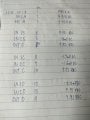
- Pin 1, 2, 3 of IC8 are all 4.35VDC
- /CONT is 3.98VDC (measured at P6 and on IC8 Pin 3 pad)

So /CONT is still going high even with pin 3 disconnected. Does this seem right?

Edit: the 3.98VDC measured at /CONT is a phantom voltage as after placing 2k resister in parallel between /cont and GND the voltage becomes a few millivolts. The buttons begin to work again if i do this by the way. but when powering off then on it looses settings. I do not know where exactly this voltage is coming from though. I would have though there would be no capacitive coupling between pin 3 that i cut and the pad but maybe im wrong. I'll go out and buy a pair of precision snips this afternoon
 
Last edited:

MrChips

Joined Oct 2, 2009
35,276
There is no phantom voltage. What you are observing is normal.
Inputs have high impedance. When there is no signal connected, an input will assume any voltage, including picking up leakage current and every RF, radio, TV, WiFi, and smart phone signal.

Getting a small side cutter and small needle nose pliers would be your best option.

Snip away the IC package leaving as much of the pin behind. Unsolder each pin from below while pulling out the pin from above. Spend as little time as possible when heating the pad from below.

When all done, clean up the holes with solder sucker or solder wick. You will find it easier to clean the holes if you add more solder and/or solder flux. Again, go easy on the heat.

Insert IC socket and solder in place.
Square up the pins of the new IC and insert into the socket.
 

Thread Starter

Tp86

Joined Sep 13, 2023
216
There is no phantom voltage. What you are observing is normal.
Inputs have high impedance. When there is no signal connected, an input will assume any voltage, including picking up leakage current and every RF, radio, TV, WiFi, and smart phone signal.
Hi mate. Im trying get my head around this. I know the inputs of my multimeter, and the inputs of the ic8 and other ic's will have high impedance inputs. But you said 'when there is no signal connected' what do you mean because I still have the inputs connected and the only one not connected is pin 3 (the output) which is the /CONT node. I can see that this node is actually connected to Pin 2 of a different IC3a (AND gate). Is this what you were referring to? But in any case, this voltage is the definition of a ghost/phantom voltage isn't it, it comes from a capacitive coupling from some source of interference. When I place the resister in parallel with the node to ground the voltage quickly disappears . If not could you please show me specifics of what you mean so I am try make some sense of it?
 

Attachments

MrChips

Joined Oct 2, 2009
35,276
That node is also connect to IC5-1. and IC5-15, along with IC3-2, all inputs.
You cannot get a reliable voltage reading of any input unless the input is connected to a voltage source or ground via a low resistance (lower than 20kΩ in this case).

The fact that a 2kΩ resistor to ground is able to pull it to zero volts means that the node is not actively driven with a voltage source. Hence the node is said to be “floating”. What the DMM is reading is a result of the total input currents in all inputs connected to the node, not some capacitance effect.

This suggests that the fault is at IC8-3.
 

Thread Starter

Tp86

Joined Sep 13, 2023
216
That node is also connect to IC5-1. and IC5-15, along with IC3-2, all inputs.
You cannot get a reliable voltage reading of any input unless the input is connected to a voltage source or ground via a low resistance (lower than 20kΩ in this case).

The fact that a 2kΩ resistor to ground is able to pull it to zero volts means that the node is not actively driven with a voltage source. Hence the node is said to be “floating”. What the DMM is reading is a result of the total input currents in all inputs connected to the node, not some capacitance effect.

This suggests that the fault is at IC8-3.
Ok this took me a while to get my head around properly. So we are talking mosfet gate to channel leakage across many of the IC inputs. Elections from the gate metal pin/pad flow through the imperfections of the insulation silicon dioxide and then to the channel region right next to the insulation layer which is p-type.

The thing I find unusual though is that it is 3.98V which seems high for this type of leakage? If across all the ic inputs the accumulated in series it would be more plausible but they are in parallel which would increase the current but not voltage?
 

Attachments

Irving

Joined Jan 30, 2016
5,195
Ok this took me a while to get my head around properly. So we are talking mosfet gate to channel leakage across many of the IC inputs. Elections from the gate metal pin/pad flow through the imperfections of the insulation silicon dioxide and then to the channel region right next to the insulation layer which is p-type.

The thing I find unusual though is that it is 3.98V which seems high for this type of leakage? If across all the ic inputs the accumulated in series it would be more plausible but they are in parallel which would increase the current but not voltage?
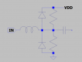
The input isn't just a gate to the MOSFET, it also includes diodes to VDD and VSS (either parasitic or real) which have some leakage The spec for the device quotes input current as +/- 15uA. A crude approximation to the input pin is something like:

1743848675870.png

Measuring with a high-impedance device will give false/meaningless readings. An open (floating) input will randomly look like a '0' or a '1' depending on external circumstances. Any induced EMF into the connected tracks will generate a static charge on the input pin. The important thing is that even a relatively high resistor will leak this charge to ground and return a definitive 0 result

Anyway, more importantly, what is the now disconnected pin 3 of IC8 actually doing? is it actually pulling down when the input (pins 1 & 2) are high? Check it with a pull-up to VDD of around 10k. If that's not getting down to 0.5v or so, IC8 pin 3 is shot.
 

Thread Starter

Tp86

Joined Sep 13, 2023
216
The input isn't just a gate to the MOSFET, it also includes diodes to VDD and VSS (either parasitic or real) which have some leakage The spec for the device quotes input current as +/- 15uA. A crude approximation to the input pin is something like:

1743848675870.png


Measuring with a high-impedance device will give false/meaningless readings. An open (floating) input will randomly look like a '0' or a '1' depending on external circumstances. Any induced EMF into the connected tracks will generate a static charge on the input pin. The important thing is that even a relatively high resistor will leak this charge to ground and return a definitive 0 result
Thank you for explaining Irving. I did some research and have learn many IC's have ESD diodes to protect the gate of the mosfets. I didnt know that. That makes more sense as to why I was reading about 4V.

Anyway, more importantly, what is the now disconnected pin 3 of IC8 actually doing? is it actually pulling down when the input (pins 1 & 2) are high? Check it with a pull-up to VDD of around 10k. If that's not getting down to 0.5v or so, IC8 pin 3 is shot.
I tested the voltage of pin 1, pin 2, pin 3 and all were 4.35V DC with the scope powered on (I did not use a resister for this test)
Then I tested /CONT and noticed it was 4Vdc (this is because of the ESD diodes like you explained from other inputs)

Then I used a 2K resister from /CONT to gnd to dissipate the voltage and it came close to 0V. The buttons came response which is great but after powering off it doesnt remember the settings. So I got ahead of myself and ordered 2 of these nand IC's in so i have a spare in case it happens again.

I do not know if that chip is the only fault or if it even is the fault. I see your logic now in pulling up pin 3 to Vdd through resister cause you can determine if its an active supply behind it. I'll try in the morning!
 
Top