Push buttons on Trio CS-2070 Oscilloscope are not responding and some constantly engaged

Thread Starter

Tp86

Joined Sep 13, 2023
210
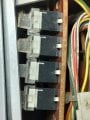
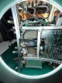
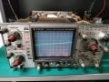
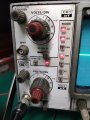
Today I purchased a 'Trio CS-2070' which is made by Kenwood. When I bought it the seller told me it had some issues. The main issue I see with it (apart from it not being calibrated) is that the push buttons are constantly lit up and I cant get them to turn off no matter what button I press. So the scope is on a CH 1 + CH 2 mode (with the CH 2 inverted). I'm not really sure if this is something easy to fix but I doubt it. Any suggestions I could try?

The first image shows the lights that are constantly on when powered on
 

Attachments

SamR

Joined Mar 19, 2019
5,470
Looks like it needs a LOT of cleaning. From that, I'd suspect that the switches also need cleaning. Disassembly and some alcohol swabs and maybe Deoxit on the switch assemblies.
 

Irving

Joined Jan 30, 2016
4,996
You can get the service manual from here: https://www.opweb.de/en/manufacturer/kenwood/cs-2070

Looking at the circuit diagrams in that manual, all the channel selection logic is driven by those push buttons, a momentary connection to ground latching the current selection into a set of CMOS latches and generating the drive for the LEDs on the Vertical Attenuator board. That appears to also be driven by an external clock from the Horizontal Mode Control Board. There's a comprehensive step-by-step troubleshooting flow chart to guide you through. My guess is that there's a broken connection somewhere, either a ground connection or the actual clock signal itself. I'd hazard a guess this won't be too difficult a fix, as long as you can get to the boards in-situ and don't fry yourself on the CRT!
 

nsaspook

Joined Aug 27, 2009
16,249
You can get the service manual from here: https://www.opweb.de/en/manufacturer/kenwood/cs-2070

Looking at the circuit diagrams in that manual, all the channel selection logic is driven by those push buttons, a momentary connection to ground latching the current selection into a set of CMOS latches and generating the drive for the LEDs on the Vertical Attenuator board. That appears to also be driven by an external clock from the Horizontal Mode Control Board. There's a comprehensive step-by-step troubleshooting flow chart to guide you through. My guess is that there's a broken connection somewhere, either a ground connection or the actual clock signal itself. I'd hazard a guess this won't be too difficult a fix, as long as you can get to the boards in-situ and don't fry yourself on the CRT!
Wow, I haven't seen one of those old Kenwood scopes since I worked for Fujitsu in the 90's.

I hope those are mechanical switches that a drop of Deoxit can fix.
1743354692292.png

I had lots of issue with the non-mechanical (membrane) selection buttons on various gear from them and other Japanese vendors. The switch contact didn't age well.
https://forum.allaboutcircuits.com/threads/advantest-tr6142-bad-keys-replacement.175787/

1743354531716.png
 

SamR

Joined Mar 19, 2019
5,470
I've not found any suitable repair for membranes other than replacement. Didn't think it would be membrane due to the indicator light on the switch button but it appears I may be wrong.
 

nsaspook

Joined Aug 27, 2009
16,249

Thread Starter

Tp86

Joined Sep 13, 2023
210
Thanks for the replies guys. I've looked under the hood to try retrieve some more information. I also cleaned it the best I can.

- The first picture shows the best photo I can get of the switch I can get (I took it from the horizontal display section as it was less secluded as the mode one)
- The second picture shows the button cable which connects the push button switch board to one of the main board in the scope
- Third picture shows the front horizontal display panel in which the first 2 photographs ribbons/switches are related to
- Forth picture shows the whole scope lights that are on when the scope is powered on. Note: not a single push button switch makes a change when I press any button. The scope always stays with the same button illuminated no matter whether I power off the unit or press any button

I have tried spraying a little WD40 Contact Cleaner onto the push buttons and tried working it in a little but it seem to have made no difference. Perhaps I didnt get it inside enough though

MrChips: I'll try get those DC values next
 

Attachments

Last edited:

Thread Starter

Tp86

Joined Sep 13, 2023
210
You can get the service manual from here: https://www.opweb.de/en/manufacturer/kenwood/cs-2070

Looking at the circuit diagrams in that manual, all the channel selection logic is driven by those push buttons, a momentary connection to ground latching the current selection into a set of CMOS latches and generating the drive for the LEDs on the Vertical Attenuator board. That appears to also be driven by an external clock from the Horizontal Mode Control Board. There's a comprehensive step-by-step troubleshooting flow chart to guide you through. My guess is that there's a broken connection somewhere, either a ground connection or the actual clock signal itself. I'd hazard a guess this won't be too difficult a fix, as long as you can get to the boards in-situ and don't fry yourself on the CRT!
This sounds very interesting. I do not quiet understand it I'll have to read up but would a broken connection explain why none of the push buttons on the oscilloscope would be responding to touch (as there is 3 separate panels which the switch sections are mounted to (mode, horisontal display and trig mode) and each have their own data ribbon that connects to various PCB's) If the clock signal is shared between all boards that definently could be a culprit. I dont quiet understand why a clock is needed for this but I'll read some more of schematic
 

nsaspook

Joined Aug 27, 2009
16,249
Thanks for the replies guys. I've looked under the hood to try retrieve some more information. I also cleaned it the best I can.

- The first picture shows the best photo I can get of the switch I can get (I took it from the horizontal display section as it was less secluded as the mode one)
- The second picture shows the button cable which connects the push button switch board to one of the main board in the scope
- Third picture shows the front horizontal display panel in which the first 2 photographs ribbons/switches are related to
- Forth picture shows the whole scope lights that are on when the scope is powered on. Note: not a single push button switch makes a change when I press any button. The scope always stays with the same button illuminated no matter whether I power off the unit or press any button

I have tried spraying a little WD40 Contact Cleaner onto the push buttons and tried working it in a little but it seem to have made no difference. Perhaps I didnt get it inside enough though
The good news is the HV and at least some of the power supplies are working. Does the trace move side to side and up/down with the H and V adjustment knobs? Looks like the entire digital control system is not working but the basic analog sweep is.
That rust on the MU metal shield makes it looks like there might be water damage to board to wire connectors and on the PCB traces. Looks like it was left outside in the rain. Use IPA, distilled or DI water or specialized cleaners (WD-40 Specialist Contact Cleaner Spray is OK) for electronics. Do not use traditional WD-40 to clean your electronics.

You will need to carefully remove, clean and reconnect every connector inside the scope. If you're lucky it's just bad connector instead of blown parts. I hope you didn't pay too much for it.
 

Thread Starter

Tp86

Joined Sep 13, 2023
210
The good news is the HV and at least some of the power supplies are working. Does the trace move side to side and up/down with the H and V adjustment knobs? Looks like the entire digital control system is not working but the basic analog sweep is.
That rust on the MU metal shield makes it looks like there might be water damage to board to wire connectors and on the PCB traces. Looks like it was left outside in the rain. Use IPA, distilled or DI water or specialized cleaners (WD-40 Specialist Contact Cleaner Spray is OK) for electronics. Do not use traditional WD-40 to clean your electronics.

You will need to carefully remove, clean and reconnect every connector inside the scope. If you're lucky it's just bad connector instead of blown parts. I hope you didn't pay too much for it.
Yes, exactly the HV and the analog circuitry seem to work fine as I have tested position knob, volt/div, time/div on the most basic settings and appears to work. Worst case Ill use it for very simple testing (however unfortunately it doesn't seem like I'll be able to use trigger modes)

I can see what you are saying regarding rust on the shield. There is board directly under that which I can only get to if I remove the CRT. I've located the anode so i should be able to short it to ground using a large screwdriver and wire connected to ground. Or I could directly short it to the grounded chassy. Im not super confident in doing it but I have the tools and basic pricipal involved in doing it. Online I've read its not recommended to measure the anode to ground voltage using a multimeter even after discharging in case there is still high voltage there. This sort of concerns me cause you will not know what voltage is still stored in the crt
 

Attachments

Thread Starter

Tp86

Joined Sep 13, 2023
210
What I've done:
- Inspected the main board that the power supply plugs into for water damage. To me it looks clean (Picture 1 and 2)
- Measured DC voltages for plug 30 and plug 27 and all seem to be within spec (Picture 3)

Any suggestions to what to try next?
 

Attachments

nsaspook

Joined Aug 27, 2009
16,249
What I've done:
- Inspected the main board that the power supply plugs into for water damage. To me it looks clean (Picture 1 and 2)
- Measured DC voltages for plug 30 and plug 27 and all seem to be within spec (Picture 3)

Any suggestions to what to try next?
Carefully disconnect, inspect, clean and reconnect each connector you see there. This wipes the spring terminal connections to the mating posts/contacts.
Put back together all that was removed and verify you haven't broken something else.

The problem seems to be on the digital side so I would start working (reseat cleaning) the connections from the switch panels back to the digital control boards and connections for that to the analog boards. Sometimes the indicators are used for error codes. Check the service manual for this.
 

Thread Starter

Tp86

Joined Sep 13, 2023
210
Carefully disconnect, inspect, clean and reconnect each connector you see there. This wipes the spring terminal connections to the mating posts/contacts.
Put back together all that was removed and verify you haven't broken something else.

The problem seems to be on the digital side so I would start working (reseat cleaning) the connections from the switch panels back to the digital control boards and connections for that to the analog boards. Sometimes the indicators are used for error codes. Check the service manual for this.
Ok. I'll try all this. It might take me some time. I also tend to think it must be something digital for example to do with one of the many IC's. I have no idea how I would find out which one(s) though. I looked for some sort of error code based on the active led lights but I couldnt find anything

Looks fairly clean inside.

Just wondering, what is the advertised bandwidth of this scope?
Hi mate. This scope is advertised at 70Mhz
 

nsaspook

Joined Aug 27, 2009
16,249
Ok. I'll try all this. It might take me some time. I also tend to think it must be something digital for example to do with one of the many IC's. I have no idea how I would find out which one(s) though. I looked for some sort of error code based on the active led lights but I couldnt find anything


Hi mate. This scope is advertised at 70Mhz
Wish I would help more. It's a crap-shoot with these old things. My DSS5020 is still working but still has problems with the mechanical switches at startup.
1743416930370.png
https://forum.allaboutcircuits.com/...kusui-cos5020-oscilloscope.122854/post-987390
 

Thread Starter

Tp86

Joined Sep 13, 2023
210
Wish I would help more. It's a crap-shoot with these old things. My DSS5020 is still working but still has problems with the mechanical switches at startup.
View attachment 345749
https://forum.allaboutcircuits.com/...kusui-cos5020-oscilloscope.122854/post-987390
Nice scope!

Updating what I've done so far
- Unplugged and sprayed with specialist contact cleaner all plugs below CRT
- Reassembled

All the switches are still unresponsive and I must have accidentally rotated the trace as its on an angle

Im not too sure where to look next. I find it a little odd that they are all responsive as it seems unlikely they would all fail
 

Attachments

nsaspook

Joined Aug 27, 2009
16,249
1743421891337.png
1743422704426.png
1743422532100.png

I would start checking here. Power down, Unplug P1 on the X75-1120-01 board, power up to see if there is a difference in operation. The switches are normally open so unplugging that will check for bad (closed) switches. You also could try reseating the rest of the connectors on that board.
The X77-1130-01 also has switch inputs so that board also should have connectors reseated and switches checked.

Looks to be pullups on the switches that gives a logic low (0) when pressed. You can check each button with a meter from GND to each input pin on the connector while pressing and releasing each button.

1743422474978.png
1743422873092.png

1743422781904.png
 

Irving

Joined Jan 30, 2016
4,996
On the Vertical Attenuator PCB, all the connections marked in red should be at 5v and go to 0v when the relevant button is pressed. The orange ones should be 5v, the green 0v, the pale blue some voltage >= 5v (I think) and the brown approx 2.5v (or a squarish wave if you have another 'scope, or if this is working sufficiently). If all that's correct we can move on to the next level...

Screenshot 2025-03-31 141724.png
 
Top