As Irving has stated, we have only just started. At this level of diagnostics, we don't test individual components. We check for functional behaviour of circuits.
The standard procedure is to check all operational voltages. Once they have been verified, in your case, I am 99% certain that this is a logic problem. Since the components are standard discrete logic ICs, there is a good chance that we can pinpoint the problem.
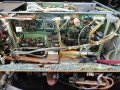
Once you have the VERTICAL ATTENUATOR UNIT board in a safe position where the ICs can be tested while fully powered, we can proceed.
CAUTION: It is imperative that you do not create accidental shorts while probing at the circuits. This will only make matters worse.
In order to examine pulsed outputs, you will need a working oscilloscope. Without that, we will have to make do with static measurements using a DMM set to measure voltage.
STEP #1
The first step is to check the supply voltages at the logic ICs. Vcc is 5 V. Thus, 4.95 V is perfectly acceptable.
STEP #2
We have two paths to check, the ADD signal and the CH2 INV signal. Let us focus on the CH2 INV signal alone for now. It is very likely that there is one common fault that is inhibiting both functions.
Follow the signal path of CH2 INV.
At IC2d pin-9, the voltage should be +5 V (nominal) and goes to 0 V when the CH2 INV button is pressed.
For safety, it is better to test the voltage at R92.
Next, the signal at IC2d pin-8 and IC7d pin-13 should be the opposite, i.e. the voltage should be +5 V when the button is pressed.
IC7 is an AND gate. If the voltage at IC7 pin-8 and pin-12 is not at +5 V, the signal will not propagate through the AND gate.
I will put my money on this being the case.
I decided to give this a go first before I attempt Irvings analysis on the horisontal mode control board as its simpler for me to get some practice in first.
Results
- The IC7 (AND gate) seems to work fine!
- The IC2 seems to work fine as an inverter however when pressed Pin goes to 0.897Vdc instead of 0Vdc. Seems unusual?
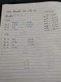
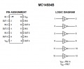
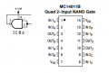
Side note: that pinout I drew is for an unrelated chip (sorry I thought they were all the same) I'll attach the pinout for IC2 chip (MC14584B)
My guess is that this will all check out OK, and because CONT is high at IC7d pin 12, IC10a will happily toggle. BUT, because /CONT is also high (which it shouldn't be) the buffer, IC11d, on IC10a Q output blocks further transmission of this signal (and all like it) to the actual memory circuit on the other board
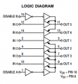
Yes you are completely correct Pin 1 and Pin 15 of the MC14503B buffer IC are to disable the A and B channels respectively which would block the signal from going through if it were high (which it is)
I decided to give this a go first before I attempt Irvings analysis on the horisontal mode control board as its simpler for me to get some practice in first.
Results
- The IC7 (AND gate) seems to work fine!
- The IC2 seems to work fine as an inverter however when pressed Pin goes to 0.897Vdc instead of 0Vdc. Seems unusual?
Side note: that pinout I drew is for an unrelated chip (sorry I thought they were all the same) I'll attach the pinout for IC2 chip (MC14584B)
When the button is pressed, it pulls a 220kΩ resistor to GND. The gate input is pulled up via a 820kΩ resistor.
Hence the 0.9V showing is correct.
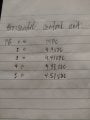
One problem though is that showing 4.08 V and 4.49 V on Vcc is inconsistent and also too low for 5V logic.
IC5 is SN7404N and IC9 is SN7432N. These require Vcc to be 5V. We need to look into this in more detail.
Look at connector P5. Measure the +5V coming in.
Also, measure +5VL at P6.
The logic chips are all MC14000 series CMOS spec'd for 3 - 18v VDD, so 4.95v on 5v rail is of no consequence, IMHO.
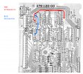
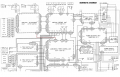
More concerning, to me, is the fact that the CONT and /CONT signals are both at 4.96v.... when you look at the source of these they come from the input and output of an inverter, IC8a, on the Horizontal Mode Control board, see highlighted schematic below, so should be complementary, shouldn't they?
It seems to me that +5.2VL and +VM are both driven via diodes (D20, D31) from +5VS via L1. As far as I can make out this is some sort of power interlock, requiring the 2 x 5v rails to be present at the collector of Q4, to change the state at the emitter, which is CONT and then the output of IC8a is /CONT.
CONT appears to be instrumental in enabling clock pulses to several flip-flops, while /CONT when low enables the outputs of several drivers. Could this be the source of the problem?
I think that Q4 is ok.
The problem is with the signal at IC8 pin-3 being stuck HIGH.
There could be only two reasons for this as far as I can see. Either IC8a is bad or there is a load pulling the signal HIGH.
Back to the Vertical Attenuation board:
- I've tested Flip flop (IC10) all working perfectly
- The buffer (IC11) is working properly from what I can test CONT bar Pin 15 is high so no matter the value of input (pin 12) the output (pin 11) is always low
Side note. That buffer IC has alot of AC type voltages around 0.6VAC on some of the other inputs I think it was. I havent looked further into that it might be the square waves you mentioned earlier?
Horisontal Mode Control Unit:
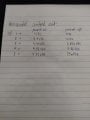
- I measured Pin 1, 2, 3, 14 and all are around 4.35VDC
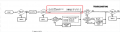
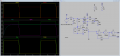
The troubleshooting flow chart in section 5-1 (page 34 of PDF) shows what should happen with CONT and /CONT. And I verified this with the simulation below. So there's something definitely wrong there. Suggest you disconnect P6 at the Horizontal Mode Control and verify, +VM, +5.2VL, CONT and /CONT are correct. If that's so, reconnect P6 at the HMC and disconnect P6 at Vertical Attenuator and verify same on the end of the cable. If that checks out there's a fault on the VA board, to be tracked down..
The troubleshooting flow chart in section 5-1 (page 34 of PDF) shows what should happen with CONT and /CONT. And I verified this with the simulation below. So there's something definitely wrong there. Suggest you disconnect P6 at the Horizontal Mode Control and verify, +VM, +5.2VL, CONT and /CONT are correct. If that's so, reconnect P6 at the HMC and disconnect P6 at Vertical Attenuator and verify same on the end of the cable. If that checks out there's a fault on the VA board, to be tracked down..
Thanks for putting this into LTSpice. Very cool simulation. I had a feeling Cont and Cont bar was used as a state to determine if the machine is on or off.
I unplugged P6 plug on horisontal control unit and tested the pins that header. I got same results. Both CONT and /CONT are high still. Would this mean the fault must be on the hcu as unplugging p6 on the hcu or vertical attenuator unit both disconnent the cont and /cont signal from the vertical attenuator unit
Please let me know if you have any more ideas. I need to get some sleep now though as its 11:49am
When the button is pressed, it pulls a 220kΩ resistor to GND. The gate input is pulled up via a 820kΩ resistor.
Hence the 0.9V showing is correct.
One problem though is that showing 4.08 V and 4.49 V on Vcc is inconsistent and also too low for 5V logic.
IC5 is SN7404N and IC9 is SN7432N. These require Vcc to be 5V. We need to look into this in more detail.
Look at connector P5. Measure the +5V coming in.
Also, measure +5VL at P6.
There's a lot more to try but at least now it's useful as a scope.
The low 5.2V (the extra 0.2 volts is usually a part of the reliability/temperature range of operation design requirements) could be an indicator of trouble elsewhere. Did you measure that voltage unloaded (with the connector removed) or was it connected an powering the other boards. If the disconnected connector voltage reads 5.2V on that pin then the 5.2V bus might be loaded down due to a high current fault(s) somewhere else. I've used voltage drops like that to narrow down higher than normal fault conditions by disconnecting boards one by one.
Im pretty sure I tested this voltage under load with the connector still plugged in. Its a big of a pain to unplug it as ill have to discharge and remove the tube again to get access. I'll try that next though if we find a solution.
Im pretty sure I tested this voltage under load with the connector still plugged in. Its a big of a pain to unplug it as ill have to discharge and remove the tube again to get access. I'll try that next though if we find a solution.
It's not a big thing if you've already narrowed down the problem to a specific board but there seems to be something causing a current drain on the logic voltage bus if the schematic voltage of 5.2v is the equipment standard logic voltage from that regulator board. It might just have shifted low over the years or was never was 5.2V when the gear was new. Just one more data point to confuse and chase. Feels like a Sherlock Holmes movie, looking for the real killer(s).
Back to the Vertical Attenuation board:
- I've tested Flip flop (IC10) all working perfectly
- The buffer (IC11) is working properly from what I can test CONT bar Pin 15 is high so no matter the value of input (pin 12) the output (pin 11) is always low
Side note. That buffer IC has alot of AC type voltages around 0.6VAC on some of the other inputs I think it was. I havent looked further into that it might be the square waves you mentioned earlier?
Horisontal Mode Control Unit:
- I measured Pin 1, 2, 3, 14 and all are around 4.35VDC
Hi Sarah. Yes it was very dirty when I got it. I've not gone in and cleaned all the ribbons properly yet I only used compressed air. I also thought there were potential tears or corrosion on the flex cables but it is only dirt. The issue (as credit given to Irving) seems to be with /CONT staying high when is telling the buffers to disable and block further propagation. /CONT is on a data bus with normal insulated copper wiring and plug (P6)
First thing is to give that PCB a good clean to ensure no corrosion or dirt is shorting /CONT high. Next is to examine it closely to check for any cracks, or broken vias.

 Facebook
 Google
 GitHub
 Linkedin