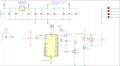
Project the circuit for a fan controller

wayneh

Joined Sep 9, 2010
17,498
If the fan motor i a brushless DC type, it already has electronic commutation and probably some components to protect the internal transistors. In addition, a protection diode could be put across the mosfet and protect it just a well, or even netter.
Is it ok to PWM such a motor?
 

MisterBill2

Joined Jan 23, 2018
18,502
It should be OK, there are quite a few applications that do run them at lower speeds to reduce the noise until max cooling is needed. In the Worst case, you will need to adjust the PWM frequency.
 

Thread Starter

PsySc0rpi0n

Joined Mar 4, 2014
1,762
Much. R7 could be a much lower value and possibly eliminated. Do you know the specs of that output from your micro? The only reason to limit current with R7 would be to protect that output. You can estimate the current you need from the gate capacitance and PWM frequency. If the micro can’t keep up, you may need an additional transistor to drive the gate.

Don’t forget the flyback diode around the motor poles. It’ll protect your MOSFET.
If the fan motor i a brushless DC type, it already has electronic commutation and probably some components to protect the internal transistors. In addition, a protection diode could be put across the mosfet and protect it just a well, or even netter.
I got confused.
One diode across fan terminals or across Mosfet Drain and Source ? Or both?

@wayneh you mean the resistor at the mosfet gate? I thought I see somewhere to use a considerable big resistor there. If I find where I saw it, I'll post here. I can't find the site, right now!

Edited;

I found something else more advanced, I shoul say:
1620154204582.png

Should I try something like this, or absolutely not needed??
 
Last edited:

wayneh

Joined Sep 9, 2010
17,498
... you mean the resistor at the mosfet gate? I thought I see somewhere to use a considerable big resistor there. If I find where I saw it, I'll post here. I can't find the site, right now!
You may have confused it with the one in the latest schematic, which is a good idea to include. It prevents the gate from floating if the state of the micro output pin goes "undetermined". That floating risks the MOSFET potentially being in some intermediate state between on or off, thereby causing it to overheat.

I'm the wrong one to ask about snubber arrangements but I do know that the inductive pulse you want to get rid of is developed in the coils of the motor when it's turned off. The diode on the motor poles absorbs that spike and prevents it from escaping to other components. Do you still need D1? I don't think so but it doesn't hurt.
 

Thread Starter

PsySc0rpi0n

Joined Mar 4, 2014
1,762
You may have confused it with the one in the latest schematic, which is a good idea to include.
I'm completely lost now.
Are we talking here about what? The 300Ω resistor I placed between 12V and the positive terminal of the fan?
If so, that is to avoid higher current than the 40mA (stated at the fan label) to come to the fan and potentially damage it. 12V/40mA = 300Ω.

If you say I don't need it, what stops currents higher than 40mA to come from the 12V supply?

It prevents the gate from floating if the state of the micro output pin goes "undetermined". That floating risks the MOSFET potentially being in some intermediate state between on or off, thereby causing it to overheat.
Now, we are talking about the gate ressistor of 10kΩ I added, right? I don't have any R7 in the circuit. The resistor at the gate is not labelled yet and the resistor that I added between the 12V and the fan is R2.

I'm the wrong one to ask about snubber arrangements but I do know that the inductive pulse you want to get rid of is developed in the coils of the motor when it's turned off. The diode on the motor poles absorbs that spike and prevents it from escaping to other components. Do you still need D1? I don't think so but it doesn't hurt.
You said here and here to use a flyback (or a reverse-biased) diode between the motor (which I assume you meant fan) terminals.
That's why I added D1 there. I don't understand why you're asking now if I need it!
 

Thread Starter

PsySc0rpi0n

Joined Mar 4, 2014
1,762
Ok, an update.

A friend of mine gave me some suggestions for improvements and this is what I have now:


There are some values, mostly the capacitors and inductor on the top of the circuit image that might need values adjustments. I need to check the datasheet of my STM32L031K6T6.


Edited;
I have things to fix in this circuit.
Ignore this for now!

Edited 2;
Images deleted to avoid confusion.
 
Last edited:

Thread Starter

PsySc0rpi0n

Joined Mar 4, 2014
1,762
Ok, I changed the circuit above and end up with this. I still not sure about 2 connections from the datasheet and I'll try to ask about them tomorrow. For now, this is what I have:

1620168780761.png

Datasheet shows this:
1620168853332.png

Meaning 1x capacitor of 100nF between each VDD pin and VSS and 1x 10μF between VDD (again) and VSS.
What I'm not sure here is from which VDD pin this 10μF capacitor connects to VSS.

Then, the inductor part was told me by a friend of mine and I trust him. He's experienced in electronics. What I'm not sure about is if I understood 100% correct the way he told me to connect the inductor and the 2x polarized capacitors.

PS:
I'll delete the images from the post above to avoid confusion.
 

wayneh

Joined Sep 9, 2010
17,498
I'm completely lost now.
Are we talking here about what? The 300Ω resistor I placed between 12V and the positive terminal of the fan?
If so, that is to avoid higher current than the 40mA (stated at the fan label) to come to the fan and potentially damage it. 12V/40mA = 300Ω.

If you say I don't need it, what stops currents higher than 40mA to come from the 12V supply?
A device rated to 12V does not need any external device to reduce the voltage below that. It will draw the current it's designed for and no. Your calculation is correct in that the motor resembles a 300Ω load. If you put that resistor in place, the combined load would be 600Ω, the current would drop to 20mA, the total power would be cut in half and the power would be split between the resistor and the motor. In other words, don't do it.

Now, we are talking about the gate ressistor of 10kΩ I added, right? I don't have any R7 in the circuit.
Oops, I read R? as R7. Yes, the gate resistor now R2. It should definitely not be more than 1kΩ and you probably don't need it. I'll look at the micro specs when I get a chance. The latest pull-down resistor R3 is OK but a lower value, maybe 10kΩ, would turn off the gate faster.

You said here and here to use a flyback (or a reverse-biased) diode between the motor (which I assume you meant fan) terminals.
That's why I added D1 there. I don't understand why you're asking now if I need it!
Fine as drawn in last schematic above. I was referring to D1 in the schematic in #43.
 

Thread Starter

PsySc0rpi0n

Joined Mar 4, 2014
1,762
A device rated to 12V does not need any external device to reduce the voltage below that. It will draw the current it's designed for and no.
I don't understand this. I'm not trying to reduce any voltage. I was thinking about protecting the fan from any high current that may come from the 12V supply. I mean, there is nothing (that I can see) that prevents a current greater than 40mA to come from the 12V supply, for whatever reason. But I understand the quote below.

Your calculation is correct in that the motor resembles a 300Ω load. If you put that resistor in place, the combined load would be 600Ω, the current would drop to 20mA, the total power would be cut in half and the power would be split between the resistor and the motor. In other words, don't do it.
I totally understand this and makes sense, but doesn't ineherently answer my initial question of protecting the fan from higher currents than 40mA.

Oops, I read R? as R7. Yes, the gate resistor now R2. It should definitely not be more than 1kΩ and you probably don't need it. I'll look at the micro specs when I get a chance. The latest pull-down resistor R3 is OK but a lower value, maybe 10kΩ, would turn off the gate faster.
Ok, I may not need it unless to protect the mcu pin. But the other resistor is needed to avoid any unwanted unknown states at the mosfet gate.

This is what datasheet says about the pin currents:
1620226365194.png

Fine as drawn in last schematic above. I was referring to D1 in the schematic in #43.
Ah ok. yeah, I won't use one there for now!

I also need to fix a few more details I just figured out that are not as good as they could be in the circuit. I'll do it when I get home.

However I would like to get some more feedback about the inductor and its role, if possible.

Thanks
Psy
 
Last edited:

wayneh

Joined Sep 9, 2010
17,498
I totally understand this and makes sense, but doesn't ineherently answer my initial question of protecting the fan from higher currents than 40mA.
The motor itself takes care of that. Like a lightbulb, it self-limits the current to provide the rated wattage. Unlike a lightbulb, the motor has an inductance in addition to a DC resistance. That means some of the 300Ω impedance is due to the inductance. But the net result is that neither a lightbulb nor motor needs a current-limiting circuit. LEDs are the opposite - they MUST be run on a controlled current supply.
This is what datasheet says about the pin currents:
Thanks for digging that out of the (long!) datasheet. So if the output voltage is 3.3V and the maximum current there is 16mA, that suggests a gate resistor of 3.3/0.016 = 206Ω. So a standard 220 or 270Ω is fine to protect the micro output. That will limit the maximum switching frequency, but that shouldn't be a problem for your application. Do you know what PWM frequency you're planning for?
https://electronics.stackexchange.c...ulate-rg-gate-driver-for-mosfet/287805#287805
http://www.novuxtech.com/electronics/mosfet-gate-driver-calculations.html
 

Thread Starter

PsySc0rpi0n

Joined Mar 4, 2014
1,762
The motor itself takes care of that. Like a lightbulb, it self-limits the current to provide the rated wattage. Unlike a lightbulb, the motor has an inductance in addition to a DC resistance. That means some of the 300Ω impedance is due to the inductance. But the net result is that neither a lightbulb nor motor needs a current-limiting circuit. LEDs are the opposite - they MUST be run on a controlled current supply.
Thanks for digging that out of the (long!) datasheet. So if the output voltage is 3.3V and the maximum current there is 16mA, that suggests a gate resistor of 3.3/0.016 = 206Ω. So a standard 220 or 270Ω is fine to protect the micro output. That will limit the maximum switching frequency, but that shouldn't be a problem for your application. Do you know what PWM frequency you're planning for?
https://electronics.stackexchange.c...ulate-rg-gate-driver-for-mosfet/287805#287805
http://www.novuxtech.com/electronics/mosfet-gate-driver-calculations.html

Ok, so this is how I have the circuit right now1620243699130.png

What else can be done to improve ? Anything else? I'm still waiting for some feedback about the inductor from my friend or from somebody else here!

Thanks
PsySc0rpi0n
 

wayneh

Joined Sep 9, 2010
17,498
What else can be done to improve ? Anything else? I'm still waiting for some feedback about the inductor from my friend or from somebody else here!
I don't want to comment on the rest of the circuit. It looks OK to me but I'm not familiar with the details of the other components. Just one minor thing - is R4 really needed? It takes some of the heat off the regulator, literally. Make sure it's rated to at least double the power you expect to be dissipated there. Otherwise it may start to look like a fuse.
 

MisterBill2

Joined Jan 23, 2018
18,502
I don't want to comment on the rest of the circuit. It looks OK to me but I'm not familiar with the details of the other components. Just one minor thing - is R4 really needed? It takes some of the heat off the regulator, literally. Make sure it's rated to at least double the power you expect to be dissipated there. Otherwise it may start to look like a fuse.
There absolutely need to be bypass capacitors very close to the voltage regulator IC, and even then, you might get a serious oscillation due to R4. I experienced that early in my career, a very strong oscillation, several megahertz, caused by a resistor in that position. The bypass caps should be 0.1 mfd and within a half inch of the regulator leads.
Other than that, the one issude with the drawing is that GROUND SYMBOLS NEVER POINT UP!! I am aware that this is a picky point to some folks, but there are a few conventions that make a lot of sense to those of us who read a lot of circuit drawings.
 

Thread Starter

PsySc0rpi0n

Joined Mar 4, 2014
1,762
There absolutely need to be bypass capacitors very close to the voltage regulator IC, and even then, you might get a serious oscillation due to R4. I experienced that early in my career, a very strong oscillation, several megahertz, caused by a resistor in that position. The bypass caps should be 0.1 mfd and within a half inch of the regulator leads.
Other than that, the one issude with the drawing is that GROUND SYMBOLS NEVER POINT UP!! I am aware that this is a picky point to some folks, but there are a few conventions that make a lot of sense to those of us who read a lot of circuit drawings.

Hello.

I will add a capacitor there and I already changed the GND symbols down. Curiously, a friend of mine told me exactly the same. heheh

I'm now waiting for the components and I'm also trying to fix a problem with my STM32CubeMX software. I installed it in the past in an external drive but now I am not using that drive anymore, so, I need to try to uninstall the remainings that I have in my main drive and reinstall the software!

PS:
This is how the circuit is now:
1620566427104.png
 
Last edited:

Thread Starter

PsySc0rpi0n

Joined Mar 4, 2014
1,762
Now that I analyse better this image, I have a question:

What means the line the red arrow points to? At a first glance, I would say it shorts the ADC VDDA with VSSA but it makes no sense, I think. Or is it what splits the outter side and the inner side of the microcontroller?

1620568709012.png
 

MisterBill2

Joined Jan 23, 2018
18,502
That line represents the border of the integrated circuit device. The small squares represent the connection pins or solder pads. So that line should be a different color or texture from those lines indicating circuit conductors. JUst as in a roadmap, border lines should appear different from roadway lines and rivers.
 

MaxHeadRoom

Joined Jul 18, 2013
28,686
A little late to the party!
As mentioned, the IC looks a little overkill! Probabally a 8 pin would have done it?
It appears you are using KiCad for the schematic?
If so, you will need to Flag the PWR and GND as power source if running it through the NET compiler.
.
 

Thread Starter

PsySc0rpi0n

Joined Mar 4, 2014
1,762
A little late to the party!
As mentioned, the IC looks a little overkill! Probabally a 8 pin would have done it?
It appears you are using KiCad for the schematic?
If so, you will need to Flag the PWR and GND as power source if running it through the NET compiler.
.
The goal on using this chip is for learning purposes. I know it's overkill for the job.

Yes, I'm using KiCAD. For now, I'm just designing the circuit. I'm not very used to KiCAD nor I have done many circuits with it, so I'm not even familiar to what that means about needing to add flags of PWR an GND. If you can be more specific and detail the steps to do that, I would be glad to do it!


Edited;

Ohh, I know... I changed the circuit a bit further like this:
 
Last edited:

Thread Starter

PsySc0rpi0n

Joined Mar 4, 2014
1,762
Ohh ok, @MaxHeadRoom

My circuit is now a bit changed and I will reset the components numbering in the schematic so that I have a more resonable numbering according the the new position of all components.

I'm still not sure if the circuit is 100% ready.
 

Attachments

Top