12hr clock in quartus showing am and pm with switch

Thread Starter

skye12

Joined Apr 27, 2026
4
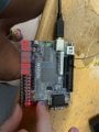
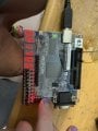
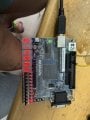
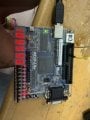
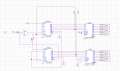
Hi i am trying to make a 12hr clock in quartus using these two chips for a 7 segment display I cant figure out hour to get the hours as i have the minutes and seconds done aleady please help. This is what ive done so far
 

Attachments

dl324

Joined Mar 30, 2015
18,297
This is what I have so far any and all help would be appreciated.
It would be helpful if you told us what wasn't working.

The hours counters are not counting from 1-12 and the AM/PM indicator isn't correct.

Why didn't you use copy and paste, or at least draw seconds and minutes circuitry the same, so it only needed to be analyzed once? Can you turn off the boxes around the symbols? They serve no purpose and are making things more confusing than the bad layout/routing are already doing.
 

dl324

Joined Mar 30, 2015
18,297
When designing clocks and counters, I prefer to use a non-standard flow for readability and place components like this:
12hourClock-1.jpg
This is a 12-hour clock using LS192 with the logic covered.

Incidentally, your seconds and minutes counters aren't working; but I think you already knew that. It doesn't make much sense to decode 9 on the LSD for seconds and minutes because LS192 is a decade counter. You didn't do that for the H1 counter. And, as you can see, decoding 5 on the S10 and M10 counters won't work.
 

dl324

Joined Mar 30, 2015
18,297
I have finished it all and have even demonstrated it to my professor here is the final product.
But it's not working.

When the seconds gets to 59, it immediately resets seconds to 0, so you're missing a second. Similarly for the minutes counter; you're missing a minute.

The hours counter doesn't count from 1-12. It counts from 0-11 (because you're loading 0 immediately after the count is 12).

You could have avoided the use of the inverter inst9 if you used the inverted output from the DFF instead.

The CLR inputs on the hours counters and DFF2 are floating. You also have preset on DFF2 connected to VCC, but it's high active, so the output should always be HIGH.

Next time, turn off that awful grid and print in black-and-white. And turn off those instance boundaries if possible. They're useless and make the schematic more difficult to read. Also, you flow is lacking and the scenic routing with unnecessary wire jogs make following the logic more difficult than it needs to be.

EDIT:
What time is 10:55:98?
IMG_1349.jpegIMG1349R.jpg
 
Last edited:

Thread Starter

skye12

Joined Apr 27, 2026
4
But it's not working.

When the seconds gets to 59, it immediately resets seconds to 0, so you're missing a second. Similarly for the minutes counter; you're missing a minute.

The hours counter doesn't count from 1-12. It counts from 0-11 (because you're loading 0 immediately after the count is 12).

You could have avoided the use of the inverter inst9 if you used the inverted output from the DFF instead.

The CLR inputs on the hours counters and DFF2 are floating. You also have preset on DFF2 connected to VCC, but it's high active, so the output should always be HIGH.

Next time, turn off that awful grid and print in black-and-white. And turn off those instance boundaries if possible. They're useless and make the schematic more difficult to read. Also, you flow is lacking and the scenic routing with unnecessary wire jogs make following the logic more difficult than it needs to be.

EDIT:
What time is 10:55:98?
View attachment 366540View attachment 366539
its 10:55:58 the camera quality cut out, I have tested and demonstrated it working in class yesterday the frequency from the clock is to fast for the seconds when i sped it up. When seconds goes to 60 it will read 00 and the 1 on the minute is loaded. I know it works as i got a 100%on the project. This is my first few weeks using quartus and my first year coding with ladder logic so I dont know how to do all your asking, this is how my brain interpretted the problem and came to a solution.
 

dl324

Joined Mar 30, 2015
18,297
I have tested and demonstrated it working in class yesterday the frequency from the clock is to fast for the seconds when i sped it up. When seconds goes to 60 it will read 00 and the 1 on the minute is loaded.
The seconds and minutes counters can never reach 60 because you're decoding 59. And you're not loading 1 or 0; you're using the CLR pins.
12HrClockMins.jpg
I know it works as i got a 100%on the project.
It doesn't work; you just fooled the examiner into complacency. The hours counter does not count from 1-12 because you're loading 0 into them.
12HrClockHours.jpg
 

dl324

Joined Mar 30, 2015
18,297
I dont know how to do all your asking
You already know how to print to a black-and-white PDF and turn off the grid. The only extra thing I asked for was to turn off the boxes around instances. You ran some wires over the instance outlines; which only served to make the schematic more confusing.

Regarding component placement and flow. Flow should generally be left-to-right and top-to-bottom. There are exceptions to this as I mentioned before. It also helps if you align components.
 

dl324

Joined Mar 30, 2015
18,297
Since the thread was bumped.

74192 (and 74LS192) have asynchronous clear and load, so you should decode 60 on seconds and minutes and 13 on hours.

This is a 12-hour clock without seconds for clarity.
LS192-12hrClock.jpg
Also note that '192 counters were designed to be cascaded without additional logic, so carry and borrow outputs can be used for the second and subsequent counters and you don't need to tie DN HIGH.

It's an absolute shame that your examiner didn't analyze your schematic and see the mistakes. If they had done that, they would have also mentioned using better component placement and appropriate flow. It seems there's little emphasis in school these days regarding drawing readable schematics.

It also helps to have symbols that were drawn intelligently.
 
Top