A further thought, I believe the output of the optocoupler will be AC and I guess that will make the relay vibrate, not what I want. So I think I’m back to using diodes but would they be better placed on the sounder input side or the relay output side?
Peter
A further thought, I believe the output of the optocoupler will be AC and I guess that will make the relay vibrate, not what I want. So I think I’m back to using diodes but would they be better placed on the sounder input side or the relay output side?
Peter
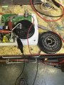
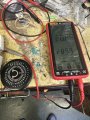
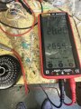
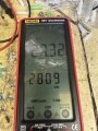
I’ve connected a 10K resistor and the sounder works. I then changed it to 15K and 22K to see how the voltage compares. I think the optocoupler will work. Please see pictures.
Peter
A further thought, I believe the output of the optocoupler will be AC and I guess that will make the relay vibrate, not what I want. So I think I’m back to using diodes but would they be better placed on the sounder input side or the relay output side?
Peter
Don't need any diodes. The LTV-814 is designed specifically for AC having 2 internal IR LEDs. The input of the relay module requires appx 2ma. The 10K resistor may need to be adjusted.
See what the voltage across the sounder is with a 4.7K resistor.
The two LEDs at the input of the LTV-814 full-wave rectify the 50Hz AC which will vibrate the relay at 100Hz.
The relay contacts might even turn on and off at 100Hz making sparks.
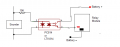
The Optocoupler has arrived and I will experiment tomorrow. I feel that just a basic circuit like this is worth starting with unless I'm missing the obvious, sorry about my drawing!
Peter.
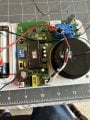
The basic circuit failed. Here is my setup. The voltage across the OC when the alarm is triggered is 0.75v AC, obviously not enough. You suggested varying the 10K resistor, what do you recommend I try?
Peter.
Again with no isolation the negative side of the sounder will be connected to the battery negative. Don't know how that will effect the siren as it appears to driven by a transformer.
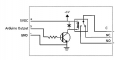
I believe this schematic is correct for the relay module the TS is using.

 Facebook
 Google
 GitHub
 Linkedin