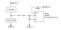
It does in reference to working in the circuit as shown in post 36.
However this circuit might work if the sounder is configured as shown.
Several more voltage measurements from the TS will confirm and may provide other options.
It does in reference to working in the circuit as shown in post 36.
However this circuit might work if the sounder is configured as shown.
Several more voltage measurements from the TS will confirm and may provide other options.
Thank you, I can see how this will trigger the relay but I have an observation. The positive to the sounder also comes from the driver circuit and I expected to use this positive side to the IN.
I feel this is exactly the circuit required, I see the LTV814 has a diode with the LED which I assume does the rectifying. I’m buying a LTV814 now.
Thank you.
Peter
I feel this is exactly the circuit required, I see the LTV814 has a diode with the LED which I assume does the rectifying. I’m buying a LTV814 now.
Thank you.
Peter
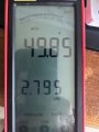
I’ve bought the PC814 as I do like the way it isolates the relay on both the + and - sides. I will try the relay supply from the batteries (6v) which may be lower with the circuit and sounder drain once triggered. If I can, I have a PC oscilloscope on an old notebook which I’ll connect up and get some data and the wave, I’d like to use it after a very long time.
I’ve bought the PC814 as I do like the way it isolates the relay on both the + and - sides. I will try the relay supply from the batteries (6v) which may be lower with the circuit and sounder drain once triggered. If I can, I have a PC oscilloscope on an old notebook which I’ll connect up and get some data and the wave, I’d like to use it after a very long time.
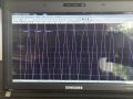
Well I’ve managed to get something, not sure what it’s saying but here’s a screenshot from my notebooks oscilloscope. Hope it gives you some information.
I have a bad feeling about this. Driving and LED or opto coupler is likely to have a large effect on the transducer. I suspect we are going to need amplification.
As I have already bought the optocoupler I’m going to wait until it arrives and see if it works. I think I’ll try your circuit as in post 36 unless you have any modifications.
Thank you for your help and time.
Peter

 Facebook
 Google
 GitHub
 Linkedin