 Facebook
 Google
 GitHub
 Linkedin
Hello AAC members,
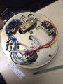
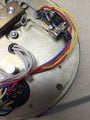
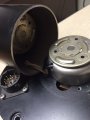
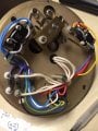
I am working on a project that involves a circuit with 6 pin outs and two relays. Right now my objective is to apply power to this circuit to flip the brass rectangular piece that can be seen in IMG_2600 below. I am new to working with electronics projects, and want to understand how the specific relays in this circuit work. Hopefully the attached images help to convey what's happening. There are two motors (shown in IMG_2605) that are used to turn the brass rectangle (lets call it a RFswitch because it's used in another application to switch the direction of an RF signal). As seen below, the position of the RFswitch determines which circuit is active to run the motors. I mapped the circuit, and applied power to the pins (IMG_2602) that I thought would activate the motors (pin B{white} and F{black, ground}) but to no avail, which makes me think that I don't quite understand this circuit. This is a bit involved, but I would greatly appreciate if anyone could help me figure out which pins I can apply power to to make this work. At minimum I would like to know how the relays work and which circuits are active when the RFswitch is in either of the two positions (I can't tell by looking). Let me know if anything needs to be clarified, and I appreciate anyone's time spent trying to figure this out.
Many thanks!
Attachments
-
 79.7 KB Views: 5
 -
 65.1 KB Views: 5
 -
 74.2 KB Views: 6
 -
 63.1 KB Views: 5
 -
 36.8 KB Views: 5
 -
 45.1 KB Views: 5
 -
 64.4 KB Views: 5
 -
 62.7 KB Views: 5


