Facebook
 Google
 GitHub
 Linkedin
Hi Everyone,
I talked to my friend about his project last night and got some more details of what he needs.
He would be operating this circuit on 3 to 4 9volt Batteries. But here is the thing. He needs the circuit to provide a constant 1.5 milliamps of current.
Let me explain a little more about this project. He works in a Micro-Lab doing testing on ultra pure water. For this project he has a beaker filled with pure water. Then inserts two rods into the water and applies DC voltage to the rods. As the conductivity of the water rises so does the current. After this process is done, he then tests the water in a TOC analyzer. What ever that is.
The problem is that the current after so many hours will go way over 1.5 milliamps. He needs it to stay put at 1.5 milliamps.
So, he wanted to know if a circuit could be made that would provide a constant 1.5 milliamps. Meaning before the rods are inserted or after the rods are inserted into the water it would provide 1.5 milliamps current.
Thanks for all of your help guys,
StephenMG


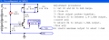
") ) turned the 10KΩ pot so it shorts emitter to +supply.
) turned the 10KΩ pot so it shorts emitter to +supply.