Facebook
 Google
 GitHub
 Linkedin
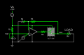
Okay this is probably a really dumb idea. I have several low-voltage projects ranging from about 3V-9V which are all in need of more permanant power sources. I also happen to have numerous old DC power supplies laying around from old laptops, monitors and such with a variety of different ratings, 12V, 14V, 24V, etc. So the idea I had was to put together a little circuit that could be spliced into any one of those cables whatsoever and provide a fixed output voltage. (In the example given I am using 24V to supply ~9V.)

Now I'll bet that using an opamp as a power supply is probably not the brightest idea you've heard of this week. But hear me out! The circuits this will be powering draw less than a couple hundred milliamps (and in fact much less than that on average). I haven't identified the particular opamp to try this out on just yet, but surely there are at least a few that can handle up to 24V and 200mA?
So....
(1) Is this just a terrible idea that should be scrapped altogether? If so then what might be some other options? Otherwise which opamps would be the best to use?
(2) Can I get a lower reference voltage than the ~5.5V that the zener provides?
(3) Is there a better/easier way to get achieve this? I still want to be able to use just about any old cable (interchangeably) in such a way that the same output voltage (+- say 1V) would be maintained?
(4) Could this idea be adapted to much higher voltages/currents?
Last edited:


")