Facebook
 Google
 GitHub
 Linkedin
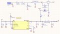
Building a networked device and want a dual power supply option. So, I’m working on a redundant power design based on Silvertel’s app note, using the AG9205 PoE module (+5v_POE on schematic below) and a Murata OKL-T/3-W12P-C 12V to 5V DC/DC converter. PoE should have priority: if both power sources are present, PoE should remain active and inhibit the 12V path via Q1.
The circuit isn't switching over correctly. Should I add a second diode at the output of the Murata module?
Currently, I have one Schottky diode (SS34-E3/57T) at the output of the AG9205 (PoE) per the app note, but no diode on the output of the Murata module. I’ve noticed some strange behavior when both supplies are present, and I’m wondering if "backfeeding" from the Murata into the PoE path might be the cause, even with the AG9205 output diode in place.
Would adding a second SS34 (after Murata VOUT, before merging into the system +5V rail) solve this? Or is something else likely at play?
Any advice appreciated!
Thanks.
Attachments
-
 211.6 KB Views: 33