Polarity protection device question

MrAl

Joined Jun 17, 2014
13,711
Almost everybody knows about the simple MOSFET/ZENER-Diode/Resistor circuit that prevents that power will flow into your
circuit when you connect the battery with reverse polarity.
That is well and good, I use it all the time on my boards, but it will not block reverse current like it can happen when you connect a power supply to a battery.

As it happened, I wanted to charge a large battery with my power supply and stupidly reversed the cables. The so-called protection diode across the outputs blew, but it did not prevent damage to the circuit.
Ever since I am looking for a better way to protect my (repaired) power supply from "everything", although it is being said, that there is always a clever idiot that beats idiot-proof designs".

An example would be the NCV68061 (datasheet attached, I don't own onsemi stocks).
The first thing I don't understand in the shown circuits are the battery and the "protected" battery. What kind of situation is that?
A solar-charged house battery and your electric vehicle? And why should both not be protected?

Figure1 in the datasheet (ideal diode) seems to be just an improvement of the mentioned MOSFET circuit in that it has a charge pump and will start at 3.2V.
It will also protect form back-flow, I guess and it WILL also protect from reverse polarity... or not?

So why is there a second suggestion for the reverse polarity option?

What I want is something that I connect to the output of my lab supply and then I can connect anything - a low or higher voltage battery, reverse or not - to that output without fear of damage. No smoke... magic or otherwise.

Do I have to chain an ideal diode plus a reverse polarity circuit?
Hello,

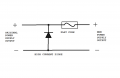
As to your second paragraph, the reverse diode may short out protecting the supply but if it blows open then it does not help at all.

The better approach is to use a high current reverse diode in parallel to the output, combined with a fast fuse in series with the output such that ANY current that flows in or out of the supply whether or not the diode is conducting or not will flow through the fuse. If the current is too high, the fuse blows, regardless what polarity it is.
 

Attachments

MisterBill2

Joined Jan 23, 2018
27,591
Okay.
But I don't think the TS is concerned about those two scenarios.
The first two paragraphs of post #1 tend to indicate that it is a big concern.
An actual compromise would be to add a "battery charging only" connection to that power supply referenced in post #1. That scheme would be fairly "idiot resistant", although not totally idiot proof.

I have realized that when the threads tend to wander a bit, it is useful to go back to post #1 to recall what the initial direction was.
 

MisterBill2

Joined Jan 23, 2018
27,591
I see no particular concern other than reverse battery connection.
That is exactly what my suggestion protects against!! It provides automatic protection against a reversed partly discharged battery connected for charging. AND, with a minor addition, it allows connecting a "dead" battery for recharging as well. I should be able to add an option to protect against an "almost stone dead" battery as well.
 

MisterBill2

Joined Jan 23, 2018
27,591
That is exactly what my suggestion protects against!! It provides automatic protection against a reversed partly discharged battery connected for charging. AND, with a minor addition, it allows connecting a "dead" battery for recharging as well. I should be able to add an option to protect against an "almost stone dead" battery as well.
It would offer protection against the revered polarity connection of an "almost stone dead" battery as well. Revered polarity could probably damage a battery management system.
 

Thread Starter

I0sens

Joined Jul 9, 2019
21
Read the first line again!! The NORMALLY OPEN contacts would not close unless the polarity was correct. S with reversed polarity response time to release will not matter BECAUSE the relay will not engage. The diode would be reverse biased and so the relay would not operate. And being a NORMALLY OPEN set of contacts, no current would flow.

I am still not sure that this would work.
Let's say the power supply is on and at changing level "24v". The polarity is correct and the relais will close.

now you connect a reverse battery. Now they fight each other with a high current and who knows, when the relais voltage will go down enough for it to disengage.
So, right now I prefer a MosFET switch like crutschow's

But my original question about the different modes of the NCV68061 is still open.
 

crutschow

Joined Mar 14, 2008
38,532
But my original question about the different modes of the NCV68061 is still open.
None of its modes appear to do what you need.
right now I prefer a MosFET switch like @crutschow's
If you use a DC SSR with a MOSFET as I show, you need to buy a fast one (microsecond response, not millisecond) so it will open fast enough to prevent damage to the supply.
What's the maximum output current of your supply?
 
Last edited:

MisterBill2

Joined Jan 23, 2018
27,591
I am still not sure that this would work.
Let's say the power supply is on and at changing level "24v". The polarity is correct and the relais will close.

now you connect a reverse battery. Now they fight each other with a high current and who knows, when the relais voltage will go down enough for it to disengage.
So, right now I prefer a MosFET switch like crutschow's

But my original question about the different modes of the NCV68061 is still open.
NO, the relay would NOT CLOSE because the battery to be charged must supply the correct polarity to operate the relay. So the relay does not operate. The diode is connected to the battery to be charged to power the relay. so the power supply voltage setting does not matter,
 
Last edited:

MisterBill2

Joined Jan 23, 2018
27,591
MB2's relay circuit will work, if you don't want to use the power supply for anything but charging a battery.
What could be quite a handy scheme would be to attach the battery charging cables with battery clips directly to the protective package, and have that connected to the supply, so that battery charging would be separated from the other supply uses.
 
Top