Oscillator won't oscillate

Tesla23

Joined May 10, 2009
560
1. Redo your coil calcs. Why are you using such a large coil? Your first one is more reasonable. 1.22uH needs 28pF to resonate at 27MHz, and you will likely have 5-10pF of strays / circuit loading. C2 = 5uF will kill any oscillation.

2. Use bigger decoupling caps, 150pF has a reactance of 39 ohms at 27MHz. It's not doing much. Use 10n or so.

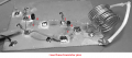
3. Tidy up the wiring around the oscillator, I have highlighted the wires carrying significant RF that need to be kept short:
1687997230673.png
I have highlighted both decoupling caps at the collector of Q1 as one is 150p, however a single 10n to ground close to Q1 and with short leads would be fine. You don't need C2 to stretch across the coil, soldering one end of the coil to the ground plane, and C2 with short leads at the other end to the ground plane is better.

This may give you some ideas as to how to keep your leads short:
1687998647664.png


Good luck.
 
Last edited:

Audioguru again

Joined Oct 21, 2019
6,826
Each half-inch wire on every part (especially on the transistors) is an inductor. The circuit must have VERY short wires.
The coil is miles away from the oscillator transistor and its tuning capacitor has extremely long wires which is why a small coil works better.
 

Attachments

Thread Starter

SamR

Joined Mar 19, 2019
5,495
Redo your coil calcs For? I actually measured the coil with my ExtechLCR200 handheld meter. The coil calculator gave me ~1.5uH but the meter gave me 1.22uH and that was what I used in the frequency calculation to solve for C. Which I really thought would be in pF and not uF!
1687998935886.png
I got 5.35 by cherry picking and doubling parallel caps.
1.22uH needs 28pF to resonate at 27MHz- That is more like what I was expecting so seems I have the wrong formula? Hmmm...
Why are you using such a large coil- I started with 5/16" ID but to get ~1.5uH would take ~20 turns. So I found a .75" piece of hard plastic tube to use a form which calculated out to 10 turns for ~1.5uH. That is easily changed and I'll try 5/16".
Tidy up the wiring around the oscillator- OK, will do. Version 2 coming up...
Single 10n to ground close to Q1 and with short leads would be fine- Will do.
Don't need C2 to stretch across the coil- OK, I wondered about that, but followed the example given. Ground is Ground at any point on the plane.

Thanks for the input. This will keep me busy between doctor's appts.
 

Thread Starter

SamR

Joined Mar 19, 2019
5,495
1688004624346.png
This just doesn't look right. I'm using the standard f=1/2π√Lt*C. Lt in this case is the entire coils measured uH. Which in this new coil is 0.674uH and it's telling me for 27MHz I need a 7.18uF capacitor? I thought it would be in pF? What am I missing?
 

Thread Starter

SamR

Joined Mar 19, 2019
5,495
It is, the ,X at the end is saying solve for X. I'm using Microsoft Mathematics and that is how it parses the equation. I could do it by hand but this is usually better. Keeps me from making calculation errors usually...
 

Thread Starter

SamR

Joined Mar 19, 2019
5,495
Ok, I put the result in the equation and solved for f and got a really screwy answer instead of 27MHz. I'm going to do it the old fashioned way...
 

Halfpint786

Joined Feb 19, 2018
109
Tesla is saying you need to multiply the capacitance with the inductance before the square root is taken in the formula for frequency. The equation you show has the x outside of the sqrt function when it should be inside it.

Here is the rearranged version of that formula to solve for L. In a spreadsheet like excel or openoffice with f(hz) in cell A1 and C(Farad) in cell B1, this would go in cell C1 "=1/(4*PI()^2*A1^2*B1)" to calculate henrys.
 

Thread Starter

SamR

Joined Mar 19, 2019
5,495
Aha! Got it, 51.6pF. That's more like it! Missed that little detail. Thanks, good call! I need to figure out how to get this calc to understand E-12 and such!
1688013222501.png
 

Thread Starter

SamR

Joined Mar 19, 2019
5,495
Once I figured out that the calculation for the tank capacitance was wrong, I changed the tank capacitor to the correct calc value and instead of bridging the coil, I went straight to the ground plane in the minimum distance. It is oscillating, however I don't think this is anywhere near what I'm trying to get!
1688026534701.png
 

Halfpint786

Joined Feb 19, 2018
109
I think i see a couple issues yet.
  • The tap point on the inductor needs to be further from the top of the inductor. Think of the inductor as an autotransformer raising the voltage. You need that voltage gain to sustain the oscillation. Having the tap a turn from the base doesn't allow for any voltage gain.
  • The emitter resistor could be bigger and the input impedance of the buffer could be a lot higher. Combined, as is, there is much less than 1kΩ shunting the tank and that lowers its Q. And with skin effect giving the coil a real value of resistance to worry about, I bet you have a single digit loaded tank Q.
  • It may be worth getting the oscillator portion working before connecting the buffer. It will help narrow down issues and give an appreciation for the loading effect it has on the oscillator.

I would try moving the coil tap to the center of the coil and going with a 4.7kΩ emitter resistor on the first transistor and a 470k for it's base bias and running it without the buffer connected. If it oscillates, see what happens when connecting the buffer.
 

Ylli

Joined Nov 13, 2015
1,092
I'm going to disagree with Halfpint. If the oscillator is squegging like that, it indicates too much feedback. Move the tap closer to the transistor base. In addition, I would suggest stiffening the transistor bias by adding a 100K resistor between the transistor base and ground and changing the original base to power resistor to 33K. For the coil, suggest something like #18, 15 turns, 0.45" diameter, stretched to 0.75" long.
Screenshot 2023-06-29 135954.jpg
 
Last edited:

Thread Starter

SamR

Joined Mar 19, 2019
5,495
OK, Version 2 a bit dark. 5/16"ID coil @ 0.693uH with 50-51pF tank capacitor. 10nF decoupling caps on the collectors. The coil is tapped near mid-point. I'm going to move the entire coil as close to the transistors as possible and eliminate component wire as much as possible. Do I need to cut the transistor leads down as well? The tank capacitor is going from the coil straight to the ground plane.
1688069429640.png
And no joy...
1688069693024.png
 

Halfpint786

Joined Feb 19, 2018
109
Ultrasonic oscillations, may need electrolytic decoupling capacitor on supply as well. Put a 10uF capacitor next to that RF decoupling cap (and maybe replace that red bit of wire with a 56Ω resistor).
 

Thread Starter

SamR

Joined Mar 19, 2019
5,495
Version 2.2, added 56Ω resistor between Q1 & Q2 collectors and put 10uF electrolytic cap on both collectors to gnd. still crap, maybe slightly better... Nope, looks identical...
1688073414214.png
 

Thread Starter

SamR

Joined Mar 19, 2019
5,495
I would suggest stiffening the transistor bias by adding a 100K resistor between the transistor base and ground and changing the original base to power resistor to 33K.
I might as well throw this at it as well... Version 2.3 coming up
 
Top