Facebook
 Google
 GitHub
 Linkedin
Firstly, this is mostly a learning exorcise in analog design. No commercial or practical application as yet. I am trying to create a mild HV supply without using IC's or micro-controllers.
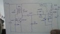
What I am attempting to do is to use a blocking oscillator to feed a more or less stable 40kHZ signal from the first stage, the BJT blocking oscillator, to a mosfet gate to switch an inductor for a higher current, unregulated (as yet) HV supply.
My problem: The positive gate signal swings too high, +28v (the neg. signal is okay at -7v). I'm concerned about damaging the gate oxide layer. I have added three zener diodes in an attempt to stop the gate from rising too high, placed before and after the gate resistor (18v+18v+4.7v). They are helping pull down the overshoot from ~44v to 28v, but I'm still still 8 volts too high. I'm stumped.
Additional notes: I tried a speed-up capacitor across the gate resistor, but this made the gate voltage swing way too high and uncontrollable. The Schottky diode on the base of the BJT squares off the waveform, making it close to 50-50%, which I like, but I don't have an understanding as why this is so. Unloaded, the circuit draws 158mA. I expect some fluctuation in the signal frequency under load, but experimentally, it ranges between ~30kHZ to 68kHZ, well outside of the audio range, which is my desire.
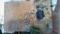
Attached are hand-drawn schematic, and a picture of my circuit.
Updated schematic to correct reversed source & drain.
What I am attempting to do is to use a blocking oscillator to feed a more or less stable 40kHZ signal from the first stage, the BJT blocking oscillator, to a mosfet gate to switch an inductor for a higher current, unregulated (as yet) HV supply.
My problem: The positive gate signal swings too high, +28v (the neg. signal is okay at -7v). I'm concerned about damaging the gate oxide layer. I have added three zener diodes in an attempt to stop the gate from rising too high, placed before and after the gate resistor (18v+18v+4.7v). They are helping pull down the overshoot from ~44v to 28v, but I'm still still 8 volts too high. I'm stumped.
Additional notes: I tried a speed-up capacitor across the gate resistor, but this made the gate voltage swing way too high and uncontrollable. The Schottky diode on the base of the BJT squares off the waveform, making it close to 50-50%, which I like, but I don't have an understanding as why this is so. Unloaded, the circuit draws 158mA. I expect some fluctuation in the signal frequency under load, but experimentally, it ranges between ~30kHZ to 68kHZ, well outside of the audio range, which is my desire.
Attached are hand-drawn schematic, and a picture of my circuit.
Updated schematic to correct reversed source & drain.
Attachments
-
 178.3 KB Views: 7
 -
 142.5 KB Views: 0
Last edited: