 Facebook
 Google
 GitHub
 Linkedin
Hello guys, this is my first post on the forum.
I am trying to reproduce a simplified version of the circuit "OSCILLATOR" attached here in pdf. This is a Colpitts oscillator based a on triode ML6696-A which datasheet is also attached. The resonating tank circuit is connected between the plate and grid.
Based on the datasheet and some info I found online, I modelled the triode on LTspice as follow:

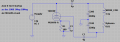
As of today my LTspice circuit looks like this :

I'm mostly interested in the resonating current across the work coil, the plate current across C2 and the grid current across C7.
Here are some observations/questions I hope someone very familiar with triode-based colpitts oscillators can help me with :
- I do observe oscillations but the resonance frequency depends on the order of the capacitors C100 and C200, if I inverse them the resonance frequency drops. To my understading this is not normal, the equivalent capacitance is C100*C200/(C100+C200). Someone has an explanation for that ?
- The plate current (50A peak) is indeed larger than the grid current (7A peak), I expect more values as stated in the ML6696-A datasheet.
However the plate current is equal to the resonating current across the work coil. If I remove the grounding between C100 and C200 I do get indeed a bigger resonating current (50A peak) than the plate current (7A peak) but then the plate and grid currents become equal.
- The current across R1 is way too big (130A) thus dissipating unrealistic amounts of power, however keeping R1 low is the only way I found to not have damped oscillations.
Does my problem come from the .sub definition of the triode, from the triode biasing, or from something I missed while trying to reproduce a simplified version of the oscillator circuit ?
Thank you very much !
/Boris
I am trying to reproduce a simplified version of the circuit "OSCILLATOR" attached here in pdf. This is a Colpitts oscillator based a on triode ML6696-A which datasheet is also attached. The resonating tank circuit is connected between the plate and grid.
Based on the datasheet and some info I found online, I modelled the triode on LTspice as follow:
As of today my LTspice circuit looks like this :
I'm mostly interested in the resonating current across the work coil, the plate current across C2 and the grid current across C7.
Here are some observations/questions I hope someone very familiar with triode-based colpitts oscillators can help me with :
- I do observe oscillations but the resonance frequency depends on the order of the capacitors C100 and C200, if I inverse them the resonance frequency drops. To my understading this is not normal, the equivalent capacitance is C100*C200/(C100+C200). Someone has an explanation for that ?
- The plate current (50A peak) is indeed larger than the grid current (7A peak), I expect more values as stated in the ML6696-A datasheet.
However the plate current is equal to the resonating current across the work coil. If I remove the grounding between C100 and C200 I do get indeed a bigger resonating current (50A peak) than the plate current (7A peak) but then the plate and grid currents become equal.
- The current across R1 is way too big (130A) thus dissipating unrealistic amounts of power, however keeping R1 low is the only way I found to not have damped oscillations.
Does my problem come from the .sub definition of the triode, from the triode biasing, or from something I missed while trying to reproduce a simplified version of the oscillator circuit ?
Thank you very much !
/Boris
Attachments
-
1.9 MB Views: 2
-
486.3 KB Views: 4
-
 18.2 KB Views: 2
Last edited:


