Facebook
 Google
 GitHub
 Linkedin
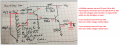
I've shown a few actual pics and the tank capacitor IS across the entire coil and the schematic needs to be updated to show that. Both transistors are DC isolated from the coil by the 0.01uF caps. I've ordered some bare 18AWG magnet wire (instead of stripping 22AWG hookup wire) to rebuild the coil and play with size and turns. I'll start with 26MHz and the 181pF tank capacitor and work from there. I didn't design the coil and agree that I think the tap should be closer to the center but I'm working with what I was given. I'm baffled at the narrow range of capacitors to make it oscillate and frankly don't understand why. I got 3.027V on one base and 3.07 on the other but yeah, both are ~19.5uA so they sure don't look to be on. I've done the basics on xstrs but still need a better grasp on them and never worked with oscillators other than a few labs showing what the various types are and do. I've been using mostly ceramic 20% 50V caps but seem to have better results with higher voltage caps? I have ordered some 200V and 1kV ceramic caps. I didn't get to it today but I also wanted to put a trimmer cap on a strip board and work with tuning it alone and parallel with a fixed cap to get a "feel" for what it can do. I have a set of 10ea of all the trimmer cap sizes to work with albeit cheap chinesium ones. Also ordered some small ceramic tuning screwdrivers as all I have is the metal blade in a plastic tube tuner now and it is always a pain to use adjusting trimmers. I try to mix up my book and bench work and this has been a good eye-opening experiment so far. The source for this has given no explanation for the coil tap right at the end of the coil so I need a better understanding of just why they did it... I also need to look at the AC component of the circuit as well...
Last edited: