Facebook
 Google
 GitHub
 Linkedin
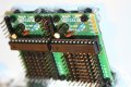
You are safe at 8/8. I generally use 10 mil traces but you are fine. Definitely connect the copper areas to ground. Though, I don't see any unconnected ones on your board.Ok, this is the smallest physically board I could make.
It's started out at 30€ for 3 boards... this version is 10€ for 3 boards... so at least it's something.
I used smaller traces considering the current used.
Ground plane on the bottom, power plane on top.
Stayed 50% on the safe zone considering the manufacturer capabilities (4/4). I'm doing 8/8.
The only thing I'm not sure, do I leave unconnected copper areas?
Did I push it too far? or it's a go?
In the electronics industry there is an old saying: Sometimes you have to shoot the engineers and ship the product. What's the worst possible thing that can happen at this point? You tossed a tenner? Not the end of the world. But the odds of that look pretty low to me.