Newbie seeking help with bench top power supply project

Thread Starter

claudeboules

Joined Mar 10, 2021
10
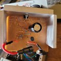
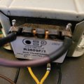
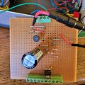
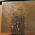
Hi, I have built the bench top power supply per the attached document but I cannot get it to work. I have tested everything I can think of. Power is coming into the transformer and is being rectified out but that is where the journey ends. It feels wrong to ask if this circuit does work and I assume it does but I do not know what else to look for. Any ideas or suggestions gratefully received.ScreenHunter 58.gif
 

Attachments

Last edited by a moderator:

Thread Starter

claudeboules

Joined Mar 10, 2021
10
Hi claude,
Do you have a photo to post showing your circuit layout?
E
Hi thank you for your response - please see the photos. I checked the required circuit breaks etc during construction and they were per the diagram. I checked the inline fuse (shown open on the photo) and that is OK. I could do a bit more dismantling and take some more photos if that would help. Best regards
 

Attachments

Thread Starter

claudeboules

Joined Mar 10, 2021
10
Is the negative output terminal connected to the DC — terminal of the bridge rectifier?
Hi Jon,

Thank you for your response. Looking at the diagram (if I have interpreted it correctly), no.

Again, if I have understood the diagram and the theory correctly the two positive outputs from the transformer are connected to the ~ inputs on the bridge rectifier and the outputs from the bridge rectifier go: negative to earth and the negative terminal of the smoothing capacitor and the positive to the fuse and the positive terminal of the smoothing capacitor.

Best regards
 

Attachments

Thread Starter

claudeboules

Joined Mar 10, 2021
10
hi claude,
How are the select switches wired?
The L200C pin#2 the Vout connection??
E
View attachment 340423View attachment 340424
Hi Eric according to the diagram L200C gives pin 2 connected to sw2A and SW3A only so in the direction of the white line you have drawn. I have not connected to anything other than the green connector block from which is it then connected to the three resistors for SW2A and then to SW3A. All the other connections are as you have drawn them. Best regards Claude
 

Thread Starter

claudeboules

Joined Mar 10, 2021
10
Hi Eric, apologies but just spotted your question about the switches:
SW1: 2 position toggle switch which allows a choice between 3v - 12v and 3v - 24v. It is wired to ~ of the bridge rectifier (P) and L&R are wired to R7;
SW2: rotary switch which allows a selection of (3) different limits and is wired to pin 2 SW3, R2 and C1;
SW3: a 3 position toggle switch which is the on/off switch and allows a choice of on with the current limit and on without the current limit. It is wired to the voltage and current meters and pins 5 and 2.

I checked to ensure the right connections several times but recognise that there may still be an error somewhere. What I am struggling to discover is what that error is and how it is causing a complete lack of any output - other than the step down of the mains voltage by the transformer. Best regards Claude
 

sparky 1

Joined Nov 3, 2018
1,218
The datasheet page 8 figure 23 shows how to configure for the supply range to go to zero.
Going below 2V

Possibly in the future someone might want a supply to adjust below the 3V limit on the circuit.
The links provided below are reference for power supply builder to help explain the basic circuit.
All the suggestions above are helpful in what the thread starter trying to accomplish
however, making a power supply capable with an extended low range below 2V is shown in the datasheet.
There is a circuit board files available. The L200C and 741 op amp version with current limiting showed promise.
I thought the cost effective heatsink shown on www.cxi1.co.uk web page is both simple and innovative.

The schematic from www.cxi1.co.uk
How To Build A Simple Current Limiting Bench Power Supply
The L200C datasheet fig 23
Adjustable voltage and current regulator
The donated circuit board files a modification based on the elektor magazine circuit.
L200 and LM741 Power Supply | Electronics Forum (Circuits, Projects and Microcontrollers)
 
Last edited:

ericgibbs

Joined Jan 29, 2010
21,391
Hi claude,
The soldering on the back of the PCB has shorts between tracks, also one track appears broken.
I have marked some suspect points.
E
1000015356.jpg
 

Thread Starter

claudeboules

Joined Mar 10, 2021
10
Hi Eric, Thank you for taking the time to look at this. I have filed the points you have flagged to remove any chance of a short. The apparent break in the track is, I think where the light has fallen on the photo. I have reassembled but still nothing. I will disassemble the parts I can again and test for continuity, resistance etc where relevant. One further question, if the circuit is working and I put my multimeter across pins 3 and 5 I should, presumably register a voltage? Best regards Claude
 
Top