 Facebook
 Google
 GitHub
 Linkedin
Hello all, new to the site. I have a little electrical knowledge, probably enough to get me in trouble, ha. So, some of the electric terminology that I use in this description probably isn't understood by some on this site. So, I will provide as much information as I can. Sorry for the long post, just trying to give as much info as I can.
I'm currently working on a project with my son and have a few questions. I have attached a drawing of what I'm trying to accomplish. His project involves a beam scale that when weight is added will allow the beam to move in the upward direction.

Here is the scale being used for the project. It's basically a lab balance beam scale.

As weight is applied, the beam will move upward toward the target point of 0.
There is a brass beam plate that extends out the back of the scale. It's a flat brass plate. In this pic, you can get an idea.

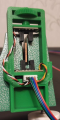
I have 2 IR optical Sensors from a 12v source. The picture attached in the details below show how it is setup.
Placement of these sensors is critical because accuracy is the upmost importance, thus the adjustment screw that is 3D printed.
The beam will go back down to the resting point when the weighted pan is removed. The object of the project is the fill the pan as fast and precise as possible to reach 200g of weight and do this 10 times. Fastest time wins.
The 12v motors will be coupled to a 1/4" brass tube about 4" long that will dispense very small lead BB's. These BB's will exit the brass tube and fall into the pan. Thus, the using of 2 separate rpm motors. The motors will not be cranking up the beam, just dispersing the BB's like an auger. So when the relays energize the state in which I want, the motors will stop immediately. Once the pan is removed, dumped and replaced back on the scale, the motor are off awaiting on the start button yet again to be pressed for the next cycle.
The Project:
Sequence
The system works flawless and works as it should, except for 1 hiccup. The one thing that I didn't think off came back to bite me in the testing. Once the pan is full of 200g of lead BB's, the circuit and the system is idle. Nothing is happening.
(this is the mess up) You have to remember to turn off the start switch before the next cycle. When I removed the pan of lead BBs to dump back into the hopper, the beam scale returned back to its resting point and the circuit started again dumping BB's all over the table.
Now that everyone is somewhat confused, here is my question.
Is it possible to replace the "start" switch, which is a simple SPST on/off switch with a Momentary push button switch? I could use a latching relay on the Mom start switch that would latch in and allow a single press of the button to energize the circuit and allow the cycle to run. But..... I need it to return to an unlatched state when the pan is removed. So every cycle must be started with a press of the mom start button.
I even thought of a timed latch relay, however in this project, speed & accuracy is the key. Too much time and your waiting. Too less time and the circuit starts again dumping BBs all over the table.
So, if you guys have any suggestions, I'm all ears. But I would like to set it up so that every press of the button will start a cycle, then once the cycle is complete, it will return to a "ready state" for the push of the next cycle.
Thanks
Titans7
I'm currently working on a project with my son and have a few questions. I have attached a drawing of what I'm trying to accomplish. His project involves a beam scale that when weight is added will allow the beam to move in the upward direction.
Here is the scale being used for the project. It's basically a lab balance beam scale.

As weight is applied, the beam will move upward toward the target point of 0.
There is a brass beam plate that extends out the back of the scale. It's a flat brass plate. In this pic, you can get an idea.

I have 2 IR optical Sensors from a 12v source. The picture attached in the details below show how it is setup.
Placement of these sensors is critical because accuracy is the upmost importance, thus the adjustment screw that is 3D printed.
The beam will go back down to the resting point when the weighted pan is removed. The object of the project is the fill the pan as fast and precise as possible to reach 200g of weight and do this 10 times. Fastest time wins.
The 12v motors will be coupled to a 1/4" brass tube about 4" long that will dispense very small lead BB's. These BB's will exit the brass tube and fall into the pan. Thus, the using of 2 separate rpm motors. The motors will not be cranking up the beam, just dispersing the BB's like an auger. So when the relays energize the state in which I want, the motors will stop immediately. Once the pan is removed, dumped and replaced back on the scale, the motor are off awaiting on the start button yet again to be pressed for the next cycle.
The Project:
- main power switch to power on everything from a 12v source.
- start switch - will be the main switch to operate the system. It will power both Mini Econ motors to drive the beam upward.
- Mom on Switch - will only be used if fine tuning is needed and will be a (Mom - on) switch that bypasses the IR sensors to get the beam at the precise location.
Sequence
- Turn on main power switch.
- Start switch will power both motors to turn simultaneously.
- While both motors are running, the beam sits idle in the bottom IR sensor. Which will allow the faster motor to run.
- When the beam starts to move upward and clears the bottom sensor, the faster motor (227-rpm) will shut off.
- Now the beam is between the bottom IR sensor and the top IR sensor while only running on the single slower 65-rpm motor. This slower turning motor allows the beam to rise at a much slower pace for a precise stop.
- The beam continues to rise on only the 65-rpm motor, until it reaches the top sensor.
Once the top sensor is breached, power is killed to the 65-rpm motor. - The top Sensor can be fine-tuned for precise stops. But if stops are not precise, the Momentary push button switch will allow “bumping” of the slower motor to get the beam to the precise location. It must override the IR sensors to get to the precise stopping point.
- Now the beam has reached its accuracy point of "0", both motors are off.
The system works flawless and works as it should, except for 1 hiccup. The one thing that I didn't think off came back to bite me in the testing. Once the pan is full of 200g of lead BB's, the circuit and the system is idle. Nothing is happening.
(this is the mess up) You have to remember to turn off the start switch before the next cycle. When I removed the pan of lead BBs to dump back into the hopper, the beam scale returned back to its resting point and the circuit started again dumping BB's all over the table.
Now that everyone is somewhat confused, here is my question.
Is it possible to replace the "start" switch, which is a simple SPST on/off switch with a Momentary push button switch? I could use a latching relay on the Mom start switch that would latch in and allow a single press of the button to energize the circuit and allow the cycle to run. But..... I need it to return to an unlatched state when the pan is removed. So every cycle must be started with a press of the mom start button.
I even thought of a timed latch relay, however in this project, speed & accuracy is the key. Too much time and your waiting. Too less time and the circuit starts again dumping BBs all over the table.
So, if you guys have any suggestions, I'm all ears. But I would like to set it up so that every press of the button will start a cycle, then once the cycle is complete, it will return to a "ready state" for the push of the next cycle.
Thanks
Titans7
Attachments
-
 572.2 KB Views: 0
 -
 572.2 KB Views: 0


