Need help with LM2917 anenometer circuit

bluejets

Joined Mar 15, 2009
9
Evo,
Would it be possible to post your new circuit. I have been following the discussions here as I have been having problems driving an LM2917 from a hall effect as well. I'm beginning to think the LM2917 doesn't go too well with hall effect switches.
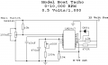
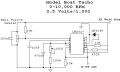
My idea was to get 0-5 volt output from 0-10,000 rpm input (which I believe is 333 hz approx). By using different combinations of R1C1 using the calculations, I get different "cut-off" points. i.e. the circuit will respond through the entire range if the output voltage is in the millivolt range but if the R1C1 values are changed to give a larger output voltage, the output will only go so far and then stops. With the circuit in attachments, this is about 1.16 Volt at approx. 2,000 rpm (70 hz)
I'm using a circuit I found at :-
http://www.niksula.hut.fi/~mdobruck/siililand/mini/diy/alien/tacho/tacho.html
and changed the input to accomodate the hall effect switch and I see it is very similar to what SgtWookie has suggested.
 

Attachments

SgtWookie

Joined Jul 17, 2007
22,230
He didn't have the schematic, I did.

Here is the latest configuration (I believe):


The configuration that you are using has a number of problems.
1) +V is connected directly to 8v. The LM2917 has a built-in Zener for regulation; it's maximum current is 25mA. You have probably destroyed the internal Zener and possibly surrounding components.

2) The 22nF cap on the input will cause problems; at higher frequencies it will keep the input from going below 0.7v. You have set the inverting input to the comparator at about 0.7v by the 10k resistor and the 1N4148 diode.

3) C1 looks quite small. Bump it up to around 0.1uF.

4) C2 looks a bit large. Reduce it to 1uF.
 

Attachments

Thread Starter

evo803

Joined Oct 7, 2009
21
Sarge thanks again ! I hooked up 2 meters to the circuit one for freqeuncy at pin-1 and one for voltage at pin-5 of the 2917. As I increase the voltage to the motor spinning a magnet. The response off the leds is quite linear.

On another note I tried using a photointerupter but the voltage would not go below 2.8vdc when blocked therefore the 2917 did not work. I am assuming this is from ambient light and I would have to enclose it completely for it to work.
 

SgtWookie

Joined Jul 17, 2007
22,230
On another note I tried using a photointerupter but the voltage would not go below 2.8vdc when blocked therefore the 2917 did not work. I am assuming this is from ambient light and I would have to enclose it completely for it to work.
Interesting.

The threshold (on pin 11) is set by R1/R2 to be Vcc/2, so 7.56/2 = 3.78v. You measured it to be 3.8v, which is fine.

The input on pin 1 just has to go above and below that threshold voltage to cause an output. 2.8v should have been low enough, and going over 4v should be high enough.
 

bluejets

Joined Mar 15, 2009
9
A bit confusing here. I saw a couple of posts back that Evo had replaced chip with NTE995 chips and said that it is all working now.. So are these pin for pin replacement for the LM2917? Did he replace the LM2917 or not?
Also, on your point No.1, pin 8 on the LM2917 is a buffer collector, pin 9 is the zener connection on 14 pin LM2917.
Point No.2, I had said that I used this circuit but I have used an input similar to the hall you show, so input cap 22nano does not exist.

As I said, the ranging works fine at low level output of tens of millivolts but fails when R1C1 are changed to accomodate larger output voltage.
 

SgtWookie

Joined Jul 17, 2007
22,230
A bit confusing here. I saw a couple of posts back that Evo had replaced chip with NTE995 chips and said that it is all working now.. So are these pin for pin replacement for the LM2917?
Yes.
Did he replace the LM2917 or not?
He posted that he did, but the NTE995 is the same as an LM2917.

Also, on your point No.1, pin 8 on the LM2917 is a buffer collector, pin 9 is the zener connection on 14 pin LM2917.
I sit corrected! I've been staring at too many schematics today...

Point No.2, I had said that I used this circuit but I have used an input similar to the hall you show, so input cap 22nano does not exist.
That's good news. I don't know why they would've used that input, unless they wanted to only see low frequency inputs and ignore higher frequency inputs.

As I said, the ranging works fine at low level output of tens of millivolts but fails when R1C1 are changed to accomodate larger output voltage.
I think you mean R1C2? In the schematic I posted, it's R5C4.

Does the voltage on pins 3&4 go higher when you change R1C2, and the output does not?

In both schematics, the internal opamp (inputs on pins 4 and 10) and it's voltage follower (collector on pin 8, emitter on pin 5) are connected as a voltage follower; the output on pin 5 should be within a few mV of pin 4.

Do you have a load other than the 10k resistor on pin 5?

Are you certain that it is a 10k resistor, and not a 100 Ohm or 10 Ohm by mistake? (easy to do...)

If the voltage on pin 3&4 is correct, and the voltage on pin 5 is low or incorrect, then there is a problem with the internal opamp/follower or the wiring connecting to the inputs/outputs.

If the voltage on pin 5 matches pins 3&4 (within a few mV), then the problem might be C1 (too low a value or bad)
 

bluejets

Joined Mar 15, 2009
9
Did he replace the LM2917 or not? He posted that he did, but the NTE995 is the same as an LM2917.

This was my point really. It seemed to me that he replaced it with a different chip and this is why it now works, which was why I asked for his circuit.
My reference to R1C1 is to the calculations and not any particular circuit.
10K is ok. Caps are all new but I will recheck all the same and test the 3-4 and 5 values.
Did think for a moment that perhaps the input may not be dropping low enough at higher speeds but this would result in low output and not "locking up" at a particular point.
 

SgtWookie

Joined Jul 17, 2007
22,230
Did he replace the LM2917 or not? He posted that he did, but the NTE995 is the same as an LM2917.

This was my point really. It seemed to me that he replaced it with a different chip and this is why it now works, which was why I asked for his circuit.
I think he burned something up in the 1st IC he was using; but he replaced it with the same type IC. NTE doesn't make their own IC's; they have manufacturers put their NTE labels/part numbers on them.

My reference to R1C1 is to the calculations and not any particular circuit.
I see.
10K is ok. Caps are all new but I will recheck all the same and test the 3-4 and 5 values.
Did think for a moment that perhaps the input may not be dropping low enough at higher speeds but this would result in low output and not "locking up" at a particular point.
Are you using the 10k resistor with the 1N4148 diode as your reference for the comparator?
If so, that could very well be your problem; you'd only have around 0.6v for the comparator reference.

Try replacing the 1N4148 with a 10k resistor. Basically, you want two resistors of the same value; whether they are 3k or 10k or 100k doesn't make much of a difference.
 

bluejets

Joined Mar 15, 2009
9
Yes. Tried lifting the bottom threshold, pin 11 but no change. One thing I have noticed is that the point at which the circuit falls over is always about the same Hz input (around 2500 rpm...80Hz)
Is it possible the circuit is loading the output of the hall effect?
 

SgtWookie

Joined Jul 17, 2007
22,230
Yes. Tried lifting the bottom threshold, pin 11 but no change. One thing I have noticed is that the point at which the circuit falls over is always about the same Hz input (around 2500 rpm...80Hz)
Is it possible the circuit is loading the output of the hall effect?
Actually, it may be that less resistance is required between Vcc and the Hall sensor output.

I just looked at Allegro's datasheet for the UGN3130. Rise/fall times for the output is 2uS max with an 820 Ohm pull-up resistor when using Vcc=12v and 20pF load capacitance. To more or less duplicate that, drop the 10k pull-up resistor down to 820 Ohms. Make certain that there is no capacitance between the Hall sensor output and the LM2917's input pin 1; just the 820 Ohm resistor.

If you don't have an 820 Ohm resistor, try anything between about 560 Ohms and 1k.
 

bluejets

Joined Mar 15, 2009
9
Cracked the problem. As I am working with much higher input Hz than with the one Evo has, the charge time of the capacitor on pin 2 starts to become relevant in relation to the input pulse. Too high a value and it doesn't get time to charge high enough due to input pulse becoming shorter. ( at least, that's my theory)
Changed the cap down to 10nano and uped the resistance to 200K and output runs up to well over 7,000 rpm (0.5V / 1000 = 3.5Volt) which is high enough for my application.
Thanks for your input, gave me the incentive to keep at it until it was solved.
I'll draw it up in the next couple of days and put it in here for future reference. Thanks again.
 

SgtWookie

Joined Jul 17, 2007
22,230
Cracked the problem. As I am working with much higher input Hz than with the one Evo has, the charge time of the capacitor on pin 2 starts to become relevant in relation to the input pulse. Too high a value and it doesn't get time to charge high enough due to input pulse becoming shorter. ( at least, that's my theory)
Changed the cap down to 10nano and uped the resistance to 200K and output runs up to well over 7,000 rpm (0.5V / 1000 = 3.5Volt) which is high enough for my application.
Thanks for your input, gave me the incentive to keep at it until it was solved.
I'll draw it up in the next couple of days and put it in here for future reference. Thanks again.
No, thank you for figuring out what the problem actually was, and providing your solution to the problem.

Feedback is really important, as it may help someone else figure out what is wrong with their circuit. That's what this forum is all about, sharing knowledge to help people over their electronic dilemmas.

I have to admit that the LM2907/LM2917 is one of those more frustrating IC's, as I don't have any of them to experiment with, and the datasheet is loaded with formulas that don't always help you arrive at a solution.

One thing to keep in mind is that the output voltage follower is more than just that; it's an opamp. In most of the schematics, it's wired as a voltage follower. However, it can also be used as a traditional opamp, which means you can give it as much gain as you like - even use it as a switch - providing that you understand it's limitations.

For example, the output won't get much higher than the Zener voltage less about 1.3v. Still, you can get a modicum of amplification from it.
 

bluejets

Joined Mar 15, 2009
9
As built and tested.
Works fine up to 8,000 rpm (test bed limit)
Uses 2 magnets on flywheel to operate the sensor. (balance reasons)
The Hall switch capacitor 100nF (across supply pins) should be mounted with the sensor and not on the driver board.
 

Attachments

SgtWookie

Joined Jul 17, 2007
22,230
As built and tested.
Works fine up to 8,000 rpm (test bed limit)
Uses 2 magnets on flywheel to operate the sensor. (balance reasons)
The Hall switch capacitor 100nF (across supply pins) should be mounted with the sensor and not on the driver board.
Holy cow - you used an OA91 Germanium diode?
Really?
Do you realize how low of a forward voltage they have at low current?
That type of diode is much better used in RF detector circuits - they are so good at low signal levels.

I'm not trying to slight your efforts in the least, but please - replace that Germanium diode with a cheap carbon resistor. Otherwise, before you know it we'll have disgruntled HAMmers lining up protesting diode abuse.
 
Top