Need help with LM2917 anenometer circuit

Thread Starter

evo803

Joined Oct 7, 2009
21
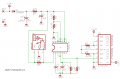
I am trying to make a simple anemometer and I can't get the circuit to work. I am not able to get a variable voltage output from lm2917 to feed into lm3914. Quick overview I am using a hall sensor to generate pulses to feed into lm555 to get square waves close to 50% duty cycle then into 2917 to output a max voltage of 10 volts to feed to lm3914 . I am using 8-2700mah AA batteries as source voltage. 60 hz is max frequency I am woking with from hall sensor. Any help will be greatly appreciated .
 

Attachments

SgtWookie

Joined Jul 17, 2007
22,230
There's a little problem with the trigger input on the 555 pin 2. Adding a 10k pull-up resistor and a diode (1N4148/1N914 would work fine, or a 1N400x) to provide a clamp and pull-up to Vcc, like this:


Oh, that's a UGN3120 Hall effect sensor by the way; you had it as UGN 1320.
 

Attachments

SgtWookie

Joined Jul 17, 2007
22,230
I'm wondering - did you look at the National Semiconductor datasheet for this IC, on page 8, for the example circuit?

The 555 timer circuit section really wasn't necessary.

I don't know why you have the output of the 555 pin 3 wired to the pin 1 of the '2907 like you do, with the 4.7k resistor, 10k resistor and 22uf cap.

You have a 15k resistor on pin 3; that is way too small of a value. Try starting off with around 220k for the moment.

Pin 3 needs to be connected to pin 4, or you won't get any output.

Pin 6 has no internal connection. Why did you wire something to it?

The pot that's connected to pin 6 and pin 10 actually should have one end on Vcc, one end on GND, the wiper on pin 10, and adjusted to 50%. Right now, pin 10 is held at 0v, so you'd never get an output even if pin 4 were connected.

You know that pin 8 is an open collector, right? It should be connected to Vcc, not the input of the 3914.

Pin 5 gets a 10k resistor to ground and connected to the 3914 input.
 

Thread Starter

evo803

Joined Oct 7, 2009
21
Thanks for the reply . I am sure you can tell that is my first electronics project. I tried to piece this circuit togehter from bits and pieces on datasheets and the web. So I really have no method to my madness. I really appreciate the response and I will be greatful for any help to get this circuit working.
 

SgtWookie

Joined Jul 17, 2007
22,230
OK, have another look at the sample application schematic that I mentioned.
You're using a 2917 instead of a 2917-8, so the pin numbers will be different.

The -8 has a number of internal connections that the non-8 parts don't have. You have to manually connect the other connections.

These 2907/2917 IC's really aren't that easy to work with, particularly for a beginner.
I'll have to dig back into the datasheet to refresh my memory, but won't be able to do so for a couple of days.
 

Thread Starter

evo803

Joined Oct 7, 2009
21
You have a 15k resistor on pin 3; that is way too small of a value. Try starting off with around 220k for the moment.
I came up with the 15k from the datasheet.

v out = F in * Vcc * R1 * C1 10.8= 60 * 12 * 15000 * .000001

10.8= 60 * 12 *220000 * .000000068

so you are saying I should change the cap value to .000000068 ?
 

SgtWookie

Joined Jul 17, 2007
22,230
No, I didn't say the cap value; the resistor value.

Leave it at 15k for the moment, and start fixing the other problems. I really don't have time at the moment to read through and analyze the datasheet again. I helped out someone with this IC many months ago, and it took a few tries before getting things right.
 

SgtWookie

Joined Jul 17, 2007
22,230
You do realize that the IC has a built-in nominal 7.56 Zener diode, right?

And you're planning on getting 10.6v out of the IC, but I don't see how.

There are other considerations - I'll have to re-visit it tomorrow. For some reason, the output voltage can't be higher than Vcc/2, which is the 7.56v / 2. I put that in a spreadsheet formula months ago, and can't remember why I did that.
 

Thread Starter

evo803

Joined Oct 7, 2009
21
Here is a modified schematic but I am still having no luck getting this to work. Any and all help with this would be greatly appreciated. I even wrote to National and there response for me to use a MCU !
 

Attachments

SgtWookie

Joined Jul 17, 2007
22,230
I've been wondering what happened to you - hope you still have some hair left. ;)

Dealing with these 2907/2917 IC's can definitely cause you to want to pull it out!

You've sort of missed out on your "window of opportunity" today as far as my (admittedly limited) expertise goes with these ICs, as I find there is always a considerable "ramping up" required, meaning studying the datasheets involved and many calculations.

I see that in your latest schematic, on the right side, the anodes of the LEDs are connected to the border. I'm pretty sure you meant for them to be supplied by 12v instead of the border, which is just a boundary for information.

Tip: When limiting LED current, it is generally preferable to put the current limiting resistors on the side farthest away from ground; in this case it would be on the +12v side of the LEDs.

Tip: The LM3914 has built-in current regulation for LEDs, which is documented in the datasheet for the LM3914. However, when powering from greater than 5v or so, it's a good idea to add current limiting resistors so that the majority of the power dissipation occurs outside of the LM3914 IC itself.
 

Audioguru

Joined Dec 20, 2007
11,248
The input pin1 of the LM2917 is triggered when it passes the voltage set on pin11. Your pin11 is floating and your input voltage from the photo-transistor does not have a resistor to ground so it is also floating floating. Then your LM2917 doesn't work.

The 27k resistor in the LM3914 circuit sets the LED current at almost nothing. Nearly every application in its datasheet uses 1.2k for an LED current of 11mA. Then the 180k resistor should also be reduced.
 

Thread Starter

evo803

Joined Oct 7, 2009
21
The input pin1 of the LM2917 is triggered when it passes the voltage set on pin11. Your pin11 is floating and your input voltage from the photo-transistor does not have a resistor to ground so it is also floating floating. Then your LM2917 doesn't work.

Could you explain this in terms that a 2 year old would understand and then maybe I will be able to figure it out.

The 27k resistor in the LM3914 circuit sets the LED current at almost nothing. Nearly every application in its datasheet uses 1.2k for an LED current of 11mA. Then the 180k resistor should also be reduced.
The 3914 works perfectly I input 0-5 volts and 0-10 leds light up,but you are saying I should change the ref voltage resistors. I do not understand why.:confused:

Thanks for the response and I really would appreciate some more handholding until I get this working.
 

Audioguru

Joined Dec 20, 2007
11,248
You have 27k ohms between pin7 and pin8 of the LM3914 that has 1.25V across it giving a current of 46.3uA.
LED current is 12 times this current which is only 0.56mA in each LED.

Every application in the datasheet uses 1.2k or less for a current in each LED of 12.5mA.
 

Thread Starter

evo803

Joined Oct 7, 2009
21
You have 27k ohms between pin7 and pin8 of the LM3914 that has 1.25V across it giving a current of 46.3uA.
LED current is 12 times this current which is only 0.56mA in each LED.

Every application in the datasheet uses 1.2k or less for a current in each LED of 12.5mA.
Here is the latest and still no luck. I am going crazy please help:eek:
 

Attachments

SgtWookie

Joined Jul 17, 2007
22,230
If you've connected the Vcc pin of the LM2917 directly to Vcc with no current limiting resistor, you have likely fried the internal Zener diode, and anything near it.

There must be a current limiting resistor between the Vcc supply pin and the actual Vcc.

I see "R" between the supply to the UGN3130 and the OUT pin. What is the value of R?
 

Thread Starter

evo803

Joined Oct 7, 2009
21
If you've connected the Vcc pin of the LM2917 directly to Vcc with no current limiting resistor, you have likely fried the internal Zener diode, and anything near it.

There must be a current limiting resistor between the Vcc supply pin and the actual Vcc.

I see "R" between the supply to the UGN3130 and the OUT pin. What is the value of R?
It is a 10k and yes I have a 470 ohm resistor on vcc to the 2917,somehow I forgot to put in the drawing.
 

SgtWookie

Joined Jul 17, 2007
22,230
OK then, how about updating your schematic so that it correctly reflects the current state of your circuit, and re-posting it?

Not trying to give you a hard time - but we really need to have a good picture of "what is" before we can suggest where you need to go.

By the way, it's not necessary to make a .pdf out of it. I really prefer schematics in a .png format; they load much more quickly, are crystal-clear sharp, and are very small in size.

[eta]
Going offline for the evening, but go ahead and update your schematic and post it.

Will take another look tomorrow.
 

SgtWookie

Joined Jul 17, 2007
22,230
OK, I've completely re-drawn your schematic.

The combination of C4/R5 might be a bit dubious. I think I'd rather see C4 at 0.1uF and R5 at 110k.

Anyway, both should give you a range of nearly 0v out to nearly 5v out of the LM2917.

I omitted the LEDs from the LM3914 output, just to keep the schematic less cluttered. Suffice it to say that they exist.

Note that the values for R7/R8 are a bit different. You had 3.9k for what I call R8; it's been reduced to 3.33k. R7 is still 1.2k.

With those values, you should get about 12.6mA current through the LEDs, and the upper threshold should be right around 5v. You might do better to use a 2.7k resistor in series with a 1k 10-turn pot to allow "tweaking" of the high reference level.

There will be a fair amount of power dissipation in the LM3914 when it's powered from 14v. I suggest that you use individual current limiting resistors of 620 Ohms on each LED.

If you're really going to power it from 9v, then R6 will need to be changed to 100 Ohms.
The circuit will draw too much current to be powered from a 9v "transistor" battery for very long.
 

Attachments

Last edited:
Top