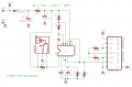
I'd inadvertently connected pin 10 of the LM2917 to the Vcc/2 reference point instead of the output. This has been corrected.
Note the formula for R6 is (Vbat - 7.56) / 15mA.
It doesn't have to be exact, but the current through the Zener must not exceed 25mA.
[eta]
The minimum supply current for the IC is 3.8mA; the maximum is 6mA. Zeners require a certain amount of current to regulate voltage properly. The necessary Zener current for good regulation is not directly disclosed in the datasheet; at least I didn't spot it after reading it for awhile. There is a chart on the 5th page, "Zener Voltage vs Temperature", which does (indirectly) shed some light on it.
It looks like the minimum total current for decent regulation is roughly 7mA. You don't want to aim for the minimum current though; when your batteries become nearly discharged, their voltage will drop considerably. If R6=130 Ohms, regulation will begin to degrade when each battery measures about 1.05v, or 8.385v across all 8 batteries.
OK, you originally told me 60Hz for the input.
Vcc should actually be somewhere around 7.56v, not 7.65v - unless the Zener current is excessive.
I used:
4.99v out = (60Hz * 7.56v) * (1uF * 11k Ohms).
4.99 = 453.6 * 0.011
4.99 = 4.99 (rounded off).
If you've changed your input frequency to 30Hz, then you should've told me. In that case, R1 (R5 in my schematic) should be 22k
[eta]
I mentioned before that I think C1 should be a lower value. The reason is that capacitance tends to be related to the physical size of the device. As you increase the capacitance, the package gets a good deal larger. Then you have to go to electrolytic caps, which tend to have a much higher tolerance than poly caps (for example).
If instead of a 1uF cap, you used a 0.1uF cap, you could use a 110k or 220k (depending whether your RPM was 60Hz or 30Hz) - the net result would be the same, but you would likely have a more accurate and more compact result.
When I went back to the hall I have 1/2 the pick up points than that of the opto one , less magnets =less weight. I thought I changed it on the latest drawing.
When I went back to the hall I have 1/2 the pick up points than that of the opto one , less magnets =less weight. I thought I changed it on the latest drawing.
Yes, you did. Sorry, I completely missed that note.
Let's do some troubleshooting.
1) What voltage do you measure on pin 9 of U2?
If you are measuring between 7.3v and 7.8v, you might be OK. If not, you've found a problem.
2) Next, measure the voltage on pin 11 of U2. You should measure about 1/2 of what you measured in 1), or about 3.8v. If not, you've found a problem.
3) Next, measure the voltage on pin 1 of U2 while slowly rotating your anemometer. The voltage needs to alternate from lower than pin 11 to higher than pin 11. If not, you've found a problem.
Yes, you did. Sorry, I completely missed that note.
Let's do some troubleshooting.
1) What voltage do you measure on pin 9 of U1?
If you are measuring between 7.3v and 7.8v, you might be OK. If not, you've found a problem.
2) Next, measure the voltage on pins 10/11 of U1. You should measure about 1/2 of what you measured in 1), or about 3.8v. If not, you've found a problem.
3) Next, measure the voltage on pin 1 of U1 while slowly rotating your anemometer. The voltage needs to alternate from lower than pins 10/11 to higher than pins 10/11. If not, you've found a problem.
OK, it looks like the internal opamp or it's voltage follower output has failed.
Pin 10 of U2 is the inverting input of the internal opamp. This should be connected to pin 5, which causes the internal opamap and voltage follower to closely follow the voltage on the noninverting input, which is pin 4.
Either that, or pin 8 is not connected to pin 9, or you inadvertently connected pin 5, or something connected to pin 5, to ground.
[eta]
Check to make sure that R3 is really 10k Ohms, and not 10 Ohms or 1 Ohm.
Pin 10 of U2 is the inverting input of the internal opamp. This should be connected to pin 5, which causes the internal opamap and voltage follower to closely follow the voltage on the noninverting input, which is pin 4.
Are you saying pin 10 and pin 5 should be connected externally ? I missed your second schematic ( pain medication from back surgery ) let me try that and see if it works. My guess is i have cooked this ic ,I have another couple on the way.
These are the voltages at 70hz at 30 hz no voltage at p5,10 no leds on.
The math for picking the components is perfect so where should I go from here ? Could the ic have been damaged by all my screw ups ?
I remember reading somewhere that thesse chips like nice square waves at 50% duty cycle could that be my issue ? How coud I troubleshoot that without a scope ?
Wait a minute - P1 is 13V?
It should measure either nearly the same as P8,P9 or nearly 0v depending on the anemometer Hall-effect sensor.
After you figure that out, let me update the schematic again; I didn't change it from 14v to 9v, so R6 should actually be around 130 Ohms.
C3, C4, and R5 are bugging me. We already discussed changing R5 from 11k to 22k because you'd changed the frequency from 60Hz to 30Hz.
I think C4 should be reduced from 1uF to 0.1uF, and R5 increased to 220k to compensate. I think having C4 larger than C3 is affecting charge pump operation.
Well, one way to ensure a nice 50% square wave would be to add a flip-flop between the output of the Hall-effect sensor and the input of the 2917. One big problem with that is you will reduce the max input frequency from 30Hz to 15Hz.
It would be a lot better if you had a few extra UGN3130 Hall effect sensors that you could add in to get back 60Hz, or perhaps 90Hz or 120Hz to more or less even things up.
You could connect multiple UGN3130's in parallel, no other parts needed. R5 would have to be changed.
For troubleshooting I am going to take a dc motor mount a hub on it and stick 6 magnets around it then attach it to a variable power supply and I should be able to dial it up to several hundred hz. I will do this in the morning.
For the final design Iwould like to use an optical solution.I have a drum with sixteen evenly spaced gaps around the circumfrence which would give me 16 inputs per rpm compared to 2 . I switched for testing because of ambient light issues with phototransistor.
I see.
Have you considered using a photointerrupter?
They are an IR emitter and phototransistor in a single package, with a slot that the interrupter passes through.
But if your project is going to be outside, you would really be better off with (a) Hall-effect sensor(s)
Found a couple of NTE995 IC's locally and guess what , success ! I first tried the original c-3, c-4, r-5, values and the first couple of leds would light up and the rest would blink until the freq. increased to 30. The output voltage on p5 was 6.3 so I did the math again and increased the r-5 to 330k and bingo. At 27 hz they all light up and at 2 hz one led starts to come on.
So c-3=.1uf
c-4=1uf
r-5=330k
pin voltages on 2917 @ 27hz
Thank you Sgt Wookie for all your handholding to try at get this circuit working for me I appreciate your help immensely ! I hope to continue learning so maybe someday I will be able to to help someone in the future.
Well, I'm certainly glad that you got it working! Congratulations!
If you look back towards the beginning, I had a hunch that what is now R5 was too low, but running through the datasheet formula my hunch was proved to be not correct.
There is also something in the datasheet about C1 (C3 in the schematic) being charged/discharged by Vcc/2; in your case Vcc is 7.56 (you just reported 7.6v) so Vcc/2 is 3.8v. Seems to me the last time I was fiddling around trying to help someone with this we had to spend several days going over the datasheet.
One thing that remains is checking the linearity of the response. You'll need to feed the input some clocks at various frequencies and see how well it tracks the changes.
One way to do that without special test equipment would be to use a CMOS 4017 5-stage Johnson counter driven that was driven by a clock. The clock could be a simple CMOS 555 timer wired to output roughly 60Hz signals.
The Johnson counter could be wired to output /2 to /10 of the input clock signal by taking the output clock from the Q0 output, and connecting one of Q1 through Q9 to the reset input.
 Facebook
 Google
 GitHub
 Linkedin