Need Help Activating an MP3 with a PIR

wayneh

Joined Sep 9, 2010
17,498
Well, when it was on the (+) side it was reading 3.4v but on the low-side (even with the 1k on the base) it keeps getting really hot so I don't have time to read it.
Since they seem to abbreviate the transistors to 2 letters; how can you tell which type it is? It could be PNp or nPN...
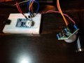
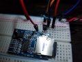
Post a closeup photo. I thought we had resolved what transistor you’re using but maybe not.
 
Thank you for that info Wayneh!
That's good to know! But I don't understand why these things keep burning up!
Below are pictures of the test rig.

I would suggest that you do it a bit more stepwise.

Make sure you have the datasheet for your 2222 and you can clearly tell which pins are C B E

Disconnect the PIR alltogether for now and just see if you can turn the MP3 with the transistor. Something like the drawing below. The dashed line represents a wire that you connect to play. The value of the resistor is important. What value would you choose based on previous discussion in the text?

mp3switch1.jpg
 

djsfantasi

Joined Apr 11, 2010
9,163
I would suggest that you do it a bit more stepwise.

Make sure you have the datasheet for your 2222 and you can clearly tell which pins are C B E

Disconnect the PIR alltogether for now and just see if you can turn the MP3 with the transistor. Something like the drawing below. The dashed line represents a wire that you connect to play. The value of the resistor is important. What value would you choose based on previous discussion in the text?

View attachment 170381
He hasn’t done the calculations for the base resistor yet. He’s still randomly trying parts and circuits.

Both you and I have tried to explain what must be done. Even the comment on how to use an NPN, was given in the first few posts. It didn’t work, so instead of learning why, the TS ignored and went back to the dysfunctional schematic.

We are going over the same ground, albeit with different people. Anyone willing to work with someone who won’t listen?
I know, I hear ya - I am hoping that he will slow down and be a little more umm purposeful in his attempts. Still, I know he is trying and I appreciate the enthusiasm - I would like to see him get the circuit working and understand why it is working [even if he goes to a relay :)
 

djsfantasi

Joined Apr 11, 2010
9,163
@Raymond Genovese Me, too.

I wish he’d test the transistor switch and get that working first. Calculate the base resistor. Calculate a resistor to give 27.4mA (or so) and try to switch ground to it, eliminating the MP3 board as an issue. I was about to suggest breaking the problem down into small parts, when I saw that in my absence, he was asking questions again that have already been answered. And that other members were giving him the same answers that he already been given.

I’m not abandoning him. I want him to read through the entire thread again, make some notes and try something. Only after checking in to see if it makes sense.

Oh, @Brianaala, were you listening? (BTW, are you Briana and actually a she?)
 

Thread Starter

Brianaala

Joined Feb 15, 2019
62
Hi folks,
Djsfantsi, I am listening and I have been doing a little more that "just randomly trying parts and circuits". You need to understand that I am very new to this and Raymond's post was the first one that suggested trying the circuit without the PIR. As DJSFantasi posted above "to be sure you have chosen the correct resistor" which suggested that I have the correct resistor, so counting on your judgement I thought I had. After we established that the MP3 was indeed only drawing ~27mA (after several tests with the multimeter) the 220 seemed to be the correct one. Then, with the transistor used on the low-side of the circuit it began to heat up so much that I went through several transistors, so I assumed that this may be the issue and that perhaps I misunderstood the label (PN2222 could be taken as either as I mentioned in the post). Therefore I switched it back, I wanted it to stop burning up; then it was suggested to go up to a 1K resistor and I did that.
I understand that it is frustrating to try to teach a novice (I am a college professor) but it is also frustrating to me when these things are not working and I do not understand why. I'm trying to do everything you suggest if I have the parts to do it (I don't have any relays) and I'm trying my best to learn and follow along. Thank you for being patient with me and I understand your frustration!
 

wayneh

Joined Sep 9, 2010
17,498
Then, with the transistor used on the low-side of the circuit it began to heat up so much that I went through several transistors, so I assumed that this may be the issue and that perhaps I misunderstood the label (PN2222 could be taken as either as I mentioned in the post). Therefore I switched it back, I wanted it to stop burning up; then it was suggested to go up to a 1K resistor and I did that.
Is the diagram provided by @Raymond Genovese in post #45 the arrangement you are using? This is very simple and "should" work. We need to sort out why it is not. In my experience it's usually a "stupid" mistake, such as reading the pins on the transistor wrong or the color bands on the resistor, or something like that. I again suggest posting a photo of your build so that another set of eyes might catch whatever the problem is.

Rather than burning up transistors, I suggest replacing the MP3 chip with an LED and a 1000Ω resistor in series. Note that the LED has a polarity. It will light up when connected directly to 5V - try it. If it doesn't, you probably have the polarity wrong so try it the other way around.

This LED will allow you to work on the transistor switch part and get that sorted out. The LED will give immediate feedback to tell you when the transistor switch is working. But with that load and the 1000Ω (or 10K) base resistor, there "should" be no risk to the transistor.
 

Thread Starter

Brianaala

Joined Feb 15, 2019
62
Hi Wayneh,
Thanks for replying! I just ran the setup that Raymond had suggested but nothing happened so I decided to just test the components, So I just ran a test taking my 5v power supply to the breadboard, with jumperwires from the rails to the MP# and it just smoked! I have no idea what is going on here! I tested the PS output and it is steady at 5.21v, I guess the extra 0.21v was too much.
 

wayneh

Joined Sep 9, 2010
17,498
I guess the extra 0.21v was too much.
I'm certain that was not it. But kudos for discovering a root cause. Did you already post the details of that mp3 player? It's either a pinout problem or it's malfunctioning. Again, nothing helps as much as a photo.

Wait a second - I just read the datasheet here:
http://www.datasheetcafe.com/gpd2846a-datasheet-gpd2846/

It appears that the IC requires digital power at 3.3V in addition to the 5V power supply. Are you providing that? Supplying 5V there instead of 3.3V could indeed be a problem.
 
Last edited:

Thread Starter

Brianaala

Joined Feb 15, 2019
62
Hi Wayneh,
I was looking at the datasheet as well, it appears that the player has an onboard voltage regulator; there is only one "bat + /GND" connection. But that can run off from 3.7 lithium or a 5v PS. I have been running these from my 5v PS since I got them (tested them all and they worked great. Considering that it is a converted PC power supply, I doubt there was a power surge, so maybe it was just a faulty component? I am trying your LED test now to try to determine if I can get the transistor to work as a switch. One question: should I run a resistor from the LED - lead or to the transistor base? Or both?
 

djsfantasi

Joined Apr 11, 2010
9,163
Brianaana, thanks for your reply. I am sorry that you misunderstood my post. I was asking a rhetorical question. “Is 220Ω correct?” I had totally expected that you would plug your values into the equation that I supplied and see that 220Ω was definitely incorrect.

220Ω is far too low. Hence, too much current is flowing into the transistor’s base and that is why it is getting hot.

The calculated resistor value is close to a 1K resistor.

I suggested that you test each of the major systems independently. You’ve done so with the MP3 player.

Check the PIR sensor. Cover it with something so it won’t trugger. Measure the voltage from the output to ground. It should be zero volts. Then repeat the test with it uncovered. The voltage should be 3.3 volts.

Breadboard the transistor switch. Connect two LEDs and current limiting resistors in parallel to simulate, approximately, a 27+ mA load. See it you can turn them on and off by connecting a 1K resistor to the base, and manually switch the other end to 3.3V and ground. You may have destroyed the 2N2222 and may have to try a new one.

Now, you know how the PIR is operating, you know your transistor switch is working. Next try combining your components.

Connect the PIR output to the base resistor in your test circuit. Can you turn the LEDs on and off by triggering the PIR?

And finally, replace the test LEDs with your MP3 player.

Let us know if any test fails. Provide pictures and schematics of each step.

With this structured approach, it will be easier to help.
 

djsfantasi

Joined Apr 11, 2010
9,163
Hi Wayneh,
I was looking at the datasheet as well, it appears that the player has an onboard voltage regulator; there is only one "bat + /GND" connection. But that can run off from 3.7 lithium or a 5v PS. I have been running these from my 5v PS since I got them (tested them all and they worked great. Considering that it is a converted PC power supply, I doubt there was a power surge, so maybe it was just a faulty component? I am trying your LED test now to try to determine if I can get the transistor to work as a switch. One question: should I run a resistor from the LED - lead or to the transistor base? Or both?
Both one to the base to set the proper current and one in series with the LED.
 

Thread Starter

Brianaala

Joined Feb 15, 2019
62
Fantastic! Thanks guys!
Djsfantasi, I did test the PIR and it puts out (by my meter) 3.41v when triggered. And yes I totally missed the sarcasm of the 220 Ohm post; "the drowning man clutches at all branches" sort of thing! I am an idiot! :)
OK so I think I will try the basic LED circuit Wayneh suggested and then move up to the steps that Djsfantasi laid out. Hopefully culminating with less blue smoke! :)
 

Thread Starter

Brianaala

Joined Feb 15, 2019
62
One further question: math is not my strong suit and I'm having a little difficulty understanding Djsfantasi's equation R(base)=(3.3-.7)/(l/10),
If I make the assumption that R=3.3/2.7= 1.2222
Now does this mean a 1.2k resistor? Also, how do I know for the equation the first integer (it seems like a span of values for R and I'm not sure where those came from)?
 

djsfantasi

Joined Apr 11, 2010
9,163
You used 3.3V as your numerator. The equation I supplied specifies that the numerator should be (3.3-0.7). Then, you’d divide the resulting 2.6V by 2.7mA, resulting in a resistor value of 963Ω. Or a 1K standard resistor.

You need to subtract the Vbe value from the input voltage. Vbe is the voltage drop between the base and emitter in a transistor. I used a general value of 0.7V, which is good enough. You could be more specific and use the Vbe value in the datasheet.

This is the kind of thing you have to be careful of. The equation (which you included in your post) specifically stated (3.3-.7). However, it looks like you just ignored the “.7” when you did your own calculation.
 

Thread Starter

Brianaala

Joined Feb 15, 2019
62
Success! I did the first LED circuit that Wayneh suggested. I used a 1K resistor on both the base and the LED to collector then emitter to ground. Now on to Djsfantasi's circuit!
 
Top