my negative supply is not regulated, why?????

MisterBill2

Joined Jan 23, 2018
27,674
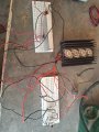
If the 120 ohm resistor burns then there must be excessive current flowing so that THE POWER GREATLY EXCEEDS THE RATINGS. For 120 ohms the current at 12 volts will be 12v/120 ohms= 100mA=0.1 amp. So the power (= V x I) would be12v x 0.1A=1.2 watts. That should not damage a 2 watt resistor.
But it seems that the 22 ohm resistor is causing the base drive of the pass transistors to be excessive,Thus the regulator is not in control at all, and so the output voltage is much greater than twelve volts. That looks like the problem.
 

crutschow

Joined Mar 14, 2008
38,542
But it seems that the 22 ohm resistor is causing the base drive of the pass transistors to be excessive
Don't see why you think that.
The voltage across the resistor starts turning on the transistors when the current through it is over 20ma, which is sufficient for the LM337 to start regulation, and provide just the base current needed for the required output current and voltage.

The sim in post #47 shows normal regulation over a large range of output voltages.
 

bertus

Joined Apr 5, 2008
22,940
hello,

i have seen these current boost circuits using a much smaller resistor than the 22 ohms.
the circuits i have seen used a resistor between 1 and 2.2 ohms.
this will put more current through the regulator.

bertus
 

panic mode

Joined Oct 10, 2011
5,033
yup... with 22 Ohm, hardly any current will be through the regulator. transistors are meant to handle excess only. while this is still allowing circuit to regulate, load sharing is not taking place.
 

panic mode

Joined Oct 10, 2011
5,033
an i strongly suggest posting some photos of the entire setup. you have blown few parts already. are you sure that others are not affected? if you mix good and damaged components, damage can spread. to troubleshoot circuit, take voltage measurements at each point and post the results.
 

MisterBill2

Joined Jan 23, 2018
27,674
The concept for the two series resistors, as it was explained a long while back, was that the current thru the boost transistors should be close to their limit at about the same total current as when the regulator IC was approaching it's current limit. From the transistor data sheet the Vbe and Ib at the maximum collector current should be available. That will tell what voltage the input resistor for the regulator must produce when the regulator current is one amp.
 

MisterBill2

Joined Jan 23, 2018
27,674
My sim shows a maximum of 300mA (mostly due to the 2N3055 base current) with 22Ω at a 4A output.
It goes to about 570mA with 2Ω.
How close to accurate is that simulator model?? That is always a question that I have. Because sometimes the model is not that very similar to reality. Especially with some kinds of devices. And to answer the question, NO!! I do not expect simulators to be really close to reality. On many occasions they might be, but not always.
 

crutschow

Joined Mar 14, 2008
38,542
How close to accurate is that simulator model?? That is always a question that I have. Because sometimes the model is not that very similar to reality. Especially with some kinds of devices. And to answer the question, NO!! I do not expect simulators to be really close to reality. On many occasions they might be, but not always.
My experience (and I have used Spice extensively since it first became available on mainframes) is that it usually is reasonably close to the real circuit results, and I see no reason that it is not here.
When the results are not correct, it is usually fairly obvious.
 

k1ng 1337

Joined Sep 11, 2020
1,038
How close to accurate is that simulator model?? That is always a question that I have. Because sometimes the model is not that very similar to reality. Especially with some kinds of devices. And to answer the question, NO!! I do not expect simulators to be really close to reality. On many occasions they might be, but not always.
How accurate was your post in #53? This is the question that I have!

People like to invalidate simulations on logical grounds but I'd rather someone provide a simulation over an extensive proof they cobbled together on paper. And let's be real, folks like yourself rarely ever present a proof at all. There is an intense irony lurking which is nicely swept under the carpet.

Here's how I look at it: How many errors are laden in a human's work VS a simulation guided by the same principles? In both cases, we arrive at the garbage in = garbage out paradigm. There is an onus to understand and apply tools as they were intended. A simulator is limited by the models it possesses, and so are humans.

Going back to your post in #53, you challenged a simulated proof with no argument of your own. What am I to make of this? I'm not laying into you personally, I just struggle to understand your thought process.
 

panic mode

Joined Oct 10, 2011
5,033
i expect better than decent accuracy of any calculator (even Bender). and if the accuracy is critical, i would check the models/measuring system over and over until satisfied or different type of measurement is deemed necessary.
 

MrAl

Joined Jun 17, 2014
13,720
Don't see why you think that.
The voltage across the resistor starts turning on the transistors when the current through it is over 20ma, which is sufficient for the LM337 to start regulation, and provide just the base current needed for the required output current and voltage.

The sim in post #47 shows normal regulation over a large range of output voltages.
Hello,

I had mentioned that just before MisterBill, but I stated it as being a possibility in a real life circuit not that it was definitely the cause. This would have to be tested in real life I think.
All he has to do is add a resistive load that would show this true or false.

We also have to remember that the transistor is driven by current while the LMxxx device is trying to regulate the voltage. If the output voltage goes too high the LMxxx device would draw less current, but then what is the minimum input current for the LMxxx device given no current out of the output.

Your idea is probably right though. A more logical reason might be that depending on how the pot is wired it could be 'open' with the arm disconnected from the substrate of the internal resistive element. This is just a guess too though. It might help if we had a photo of the circuit as wired in real life, top and bottom of the board or the plugboard or whatever.
 

Thread Starter

ommsiva

Joined Mar 13, 2024
52
Hello,

I had mentioned that just before MisterBill, but I stated it as being a possibility in a real life circuit not that it was definitely the cause. This would have to be tested in real life I think.
All he has to do is add a resistive load that would show this true or false.

We also have to remember that the transistor is driven by current while the LMxxx device is trying to regulate the voltage. If the output voltage goes too high the LMxxx device would draw less current, but then what is the minimum input current for the LMxxx device given no current out of the output.

Your idea is probably right though. A more logical reason might be that depending on how the pot is wired it could be 'open' with the arm disconnected from the substrate of the internal resistive element. This is just a guess too though. It might help if we had a photo of the circuit as wired in real life, top and bottom of the board or the plugboard or whatever.
Sir,

When I connect LM337 with out current boosting transistors, it works fine.

After connecting current boosting transistors and turning on the circuit, the output goes to 30V and ic went to breakdown.

This is same for lm317 section also.

Now problem is with current boost transistor section. Even I cross checked the base , emitter junction of current boosting transistor.

Suggest some solution.
 

Attachments

Last edited:

MrAl

Joined Jun 17, 2014
13,720
Sir,

When I connect LM337 with out current boosting transistors, it works fine.

After connecting current boosting transistors and turning on the circuit, the output goes to 30V and ic went to breakdown.

This is same for lm317 section also.

Even I cross checked the base , emitter junction of current boosting transistor.

Suggest some solution.
Hi,

Why do you have four 2N3055 transistors on one heatsink?
Also, what is the load resistance.

Sorry to say but you should never use plugboards for high current stuff. Maybe 500ma max. Everything else should be soldered.
Plugboards create problems that are hard to pinpoint sometimes. With high current loads they cannot handle the current well enough. Solder everything even the pot. If a connection becomes loose on the pot the voltage could go up very high. Also test the pot to make sure the arm of the pot always connects to the resistive substrate.
You might also start with just ONE boost transistor so there are no heatsink connection issues. I can't be sure yet what you are using four 2N3055's for are they all for just one regulator or are you trying to use two for the LM317 and two for the LM337? I don't think so but I have to ask anyway.
 

Thread Starter

ommsiva

Joined Mar 13, 2024
52
Hi,

Why do you have four 2N3055 transistors on one heatsink?
Also, what is the load resistance.

Sorry to say but you should never use plugboards for high current stuff. Maybe 500ma max. Everything else should be soldered.
Plugboards create problems that are hard to pinpoint sometimes. With high current loads they cannot handle the current well enough. Solder everything even the pot. If a connection becomes loose on the pot the voltage could go up very high. Also test the pot to make sure the arm of the pot always connects to the resistive substrate.
You might also start with just ONE boost transistor so there are no heatsink connection issues. I can't be sure yet what you are using four 2N3055's for are they all for just one regulator or are you trying to use two for the LM317 and two for the LM337? I don't think so but I have to ask anyway.
Sir,

one LM317 and four power transistor were connected so that it could bare 5 AMPS load instead of only two transistors. Same way for LM337 also.
 

MrAl

Joined Jun 17, 2014
13,720
Sir,

one LM317 and four power transistor were connected so that it could bare 5 AMPS load instead of only two transistors. Same way for LM337 also.
Ok then what you might do is start with just one transistor instead of four, then use a smaller resistive load, then increase the input voltage little by little as you check voltages and currents, and if anything starts to look bad you can just stop and investigate.

When higher power stuff is tested it common to increase the input voltage little by little instead of all at once. That way you can prevent something from blowing out if something is not right. Looking at your schematic and taking measurements should tell you what is wrong without blowing any other parts.
 

sarahMCML

Joined May 11, 2019
699
The plastic screw insulators on the 3055's look a little odd to me. There's one on the top of each transistor, which is unusual in itself. What about the other mounting screw?
 

MrAl

Joined Jun 17, 2014
13,720
The plastic screw insulators on the 3055's look a little odd to me. There's one on the top of each transistor, which is unusual in itself. What about the other mounting screw?
Yes that's one of the reasons why I was asking more about the transistors and suggesting to start with just one transistor to immediately eliminate the possible wiring errors with four transistors.
 

Thread Starter

ommsiva

Joined Mar 13, 2024
52
The plastic screw insulators on the 3055's look a little odd to me. There's one on the top of each transistor, which is unusual in itself. What about the other mounting screw?
Sir,

When there is a short between Collector and emitter of Power transistor 2N3055, I can consider the transistor went to breakdown?
 
Top