my negative supply is not regulated, why?????

MrAl

Joined Jun 17, 2014
13,720
I have replaced a new lm337, the circuit was working fine.

I have connected a load of 12v60 watt automobile lamp, lamp was fine glowing for less than 10 second. After that ic output came to-32V and 120ohm 1 watt was releasing smoke.

I could not predict what is happening, may be Lm337 could be counterfeit.
Since lm317 works fine with same lamp.
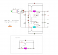
If you still suspect the LM337 then test it all by itself without external transistors and the like. Load the output to 1 amp or so and see what happens. If it works, up the current little by little and see that it goes into current limit. If it does not go into current limit then it may be fake. It should work with any load as long as the heat dissipation is taken care of with a proper heat sink. You do know that the LM337 itself has to have a heat sink too right? It may have to be a separate heat sink too so the case does not connect to the transistors in the wrong way.
 

Thread Starter

ommsiva

Joined Mar 13, 2024
52
My lm337 may be loaded by 100ma by current boosting transistors by their base terminal typically.

These current boosting transistors will bare the heat and these were fine after that.
Sir,

Please suggest simple method of deriving High current negative adjustable regulator.
 

dendad

Joined Feb 20, 2016
4,641
The circuit you have posted should work ok. An addition to help the transistors share the current better is to add a 0R5 in the emitter to power input line for each transistor.
If you are having failures, carefully check your circuit.
 

Thread Starter

ommsiva

Joined Mar 13, 2024
52
The circuit you have posted should work ok. An addition to help the transistors share the current better is to add a 0R5 in the emitter to power input line for each transistor.
If you are having failures, carefully check your circuit.
Hi Sir,

Instead of connecting emitter ballast resistor on emitter terminal, Whether it could be connected in collector terminal.

Why because the drop across emitter ballast resistor has to be developed across 22 ohm resistor.

Thank you
 

MisterBill2

Joined Jan 23, 2018
27,651
The whole concept of forcing current sharing by means of an emitter resistor is that the voltage drop in the emitter circuit reduces the base bias a bit. It is not likely that this would happen with a resistor in the collector circuit. The emitter resistor, used in a common -emitter circuit is a source of negative feedback.
 

MrAl

Joined Jun 17, 2014
13,720
Sir,

Please suggest simple method of deriving High current negative adjustable regulator.
Well yours did not look too bad except that 22 Ohm resistor. That seems too high, maybe way too high. All that has to do is develop 1v to maybe 2 volts. It does depend on the gain of the transistor too though.

Here's a drawing of the circuit but you can short out those diodes that are in series with the 2.2k resistors for your version. This also only shows one pass transistor but you can add two if you like. So this circuit should work as is except you probably have to increase the size of the fuse to handle the full power.
 

Attachments

Last edited:

MisterBill2

Joined Jan 23, 2018
27,651
What I have seen as the purpose of that 22 ohm resistor is to have the regulator go into current limiting at the same point that the "wrap-around" transistor reaches it's rated maximum current. It makes sense but at the same time, it makes the calculations a bit more complex. But it is a great theory.
 

MrAl

Joined Jun 17, 2014
13,720
What I have seen as the purpose of that 22 ohm resistor is to have the regulator go into current limiting at the same point that the "wrap-around" transistor reaches it's rated maximum current. It makes sense but at the same time, it makes the calculations a bit more complex. But it is a great theory.
Yeah I do not like it that much either although it is done a lot. It's for a 'rough' current limit certainly nothing very precise at all.
We are depending on the base emitter drop of the transistor being constant, as well as the internal current limit of the LM317 which can vary. Certainly not precise.
 

MisterBill2

Joined Jan 23, 2018
27,651
Yeah I do not like it that much either although it is done a lot. It's for a 'rough' current limit certainly nothing very precise at all.
We are depending on the base emitter drop of the transistor being constant, as well as the internal current limit of the LM317 which can vary. Certainly not precise.
That sort of current limit scheme is useful for device protection, it is not for any sort of anything like a current regulation mode of operation. At least that is the intention, which is to have the regulator do an overload/over-temp shutdown and protect the "wrap-around" transistors. That was claimed by one author many years ago.
 

MrAl

Joined Jun 17, 2014
13,720
That sort of current limit scheme is useful for device protection, it is not for any sort of anything like a current regulation mode of operation. At least that is the intention, which is to have the regulator do an overload/over-temp shutdown and protect the "wrap-around" transistors. That was claimed by one author many years ago.
Yes, that's exactly the way to describe it. It's for protection of the parts mostly. In fact, it's a sort of byproduct of the first and foremost goal which is to increase the current capability of the regulator. I prefer a more precise mechanism for current limit myself, but we have to remember this is a very, very old design and was made to be as simple as possible.
 

Thread Starter

ommsiva

Joined Mar 13, 2024
52
Yes, that's exactly the way to describe it. It's for protection of the parts mostly. In fact, it's a sort of byproduct of the first and foremost goal which is to increase the current capability of the regulator. I prefer a more precise mechanism for current limit myself, but we have to remember this is a very, very old design and was made to be as simple as possible.
I replaced another Lm337 and powered the circuit. Now 22ohm current sense of got burnt. What could the reason????
 

dl324

Joined Mar 30, 2015
18,362
Instead of connecting emitter ballast resistor on emitter terminal, Whether it could be connected in collector terminal.

Why because the drop across emitter ballast resistor has to be developed across 22 ohm resistor.
The ballast resistors are to compensate for mismatches in the BE voltage of the paralleled transistors and give better current sharing. Putting them on the collectors wouldn't help. 0.5 ohms won't have a significant impact on the turn on voltage.
 

MrAl

Joined Jun 17, 2014
13,720
I replaced another Lm337 and powered the circuit. Now 22ohm current sense of got burnt. What could the reason????
Hi,

22 Ohms would be too large for most power transistor that will have a BE voltage drop of 0.7 to maybe double that.
Try going lower on the resistance, like on the order of 1 Ohm or 2 Ohms. It might have to be a power resistor also.
This depends on how the transistor BE and that resistor share the current. If we had an emitter resistor it would make the selection simpler but would drop more voltage and dissipate even more power.

I had forgotten to eliminate that value of 22 Ohms from the schematic, sorry about that.
 

Attachments

MisterBill2

Joined Jan 23, 2018
27,651
Hi,

22 Ohms would be too large for most power transistor that will have a BE voltage drop of 0.7 to maybe double that.
Try going lower on the resistance, like on the order of 1 Ohm or 2 Ohms. It might have to be a power resistor also.
This depends on how the transistor BE and that resistor share the current. If we had an emitter resistor it would make the selection simpler but would drop more voltage and dissipate even more power.

I had forgotten to eliminate that value of 22 Ohms from the schematic, sorry about that.
I have a vague recollection that in the published version of the "wrap around" transistor application the regulator series resistor was 5 ohms and the power transistor had a one ohm emitter resistor. Of course, no matter what values the resistors have they require an adequate wattage rating. The other question is about the shunt transistor, is it getting turned on enough. In fact, if the Vbe is not going above one volt, how is the resistor getting hot?? In fact, is the transistor even conducting at all?
 

Thread Starter

ommsiva

Joined Mar 13, 2024
52
I have a vague recollection that in the published version of the "wrap around" transistor application the regulator series resistor was 5 ohms and the power transistor had a one ohm emitter resistor. Of course, no matter what values the resistors have they require an adequate wattage rating. The other question is about the shunt transistor, is it getting turned on enough. In fact, if the Vbe is not going above one volt, how is the resistor getting hot?? In fact, is the transistor even conducting at all?
Sir,

May be regulator turned as current regulator.
 

MrAl

Joined Jun 17, 2014
13,720
I have a vague recollection that in the published version of the "wrap around" transistor application the regulator series resistor was 5 ohms and the power transistor had a one ohm emitter resistor. Of course, no matter what values the resistors have they require an adequate wattage rating. The other question is about the shunt transistor, is it getting turned on enough. In fact, if the Vbe is not going above one volt, how is the resistor getting hot?? In fact, is the transistor even conducting at all?
Yes there are a number of things we do not know with this. Is the circuit even wired correctly.
If the transistor BE does not conduct, then the series resistor sees the entire current drawn by the LM317 or LM337.
 

Thread Starter

ommsiva

Joined Mar 13, 2024
52
Yes there are a number of things we do not know with this. Is the circuit even wired correctly.
If the transistor BE does not conduct, then the series resistor sees the entire current drawn by the LM317 or LM337.
Sir,

I going to built again the same circuits again. You may all give your ideas with lm317 and lm337 with current booster and 5v for digital voltage amp meter.
 

Thread Starter

ommsiva

Joined Mar 13, 2024
52
Sir,

I going to built again the same circuits again. You may all give your ideas with lm317 and lm337 with current booster and 5v for digital voltage amp meter.
Sir,

please find the attached circuit, I connected this in bread board. The 120 ohm of 1Watt was fired two times. I cant find the reason for its breakdown. got frustrated after building this circuit.
 

Attachments

Top