Facebook
 Google
 GitHub
 Linkedin
good morning to all,
I am new to this forum, studying third year college.
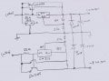
for past 2 months i was involved in studying power supply design and now I started building Lab power supply with LM317 and 337.
Positive supply was adjustable from 1.2 to 28V, but negative was starting from -8 to -24v.
Initially when i soldered and connected the circuit, my adjust pin of 337 was grounded and IC was heated, i have corrected that now and output was adjustable from -8 to -24V.
My question,
1) I have 7805 IC for powering peripheral circuit, after capacitive filtering the voltage was 35V.the output of 7805 is 10V instead of 5V, why?
2) why my negative supply was from -8 to 24V?
3) how to check LM337IC regulator?
Thanks you all
I am new to this forum, studying third year college.
for past 2 months i was involved in studying power supply design and now I started building Lab power supply with LM317 and 337.
Positive supply was adjustable from 1.2 to 28V, but negative was starting from -8 to -24v.
Initially when i soldered and connected the circuit, my adjust pin of 337 was grounded and IC was heated, i have corrected that now and output was adjustable from -8 to -24V.
My question,
1) I have 7805 IC for powering peripheral circuit, after capacitive filtering the voltage was 35V.the output of 7805 is 10V instead of 5V, why?
2) why my negative supply was from -8 to 24V?
3) how to check LM337IC regulator?
Thanks you all
Attachments
-
 1.2 MB Views: 67