my negative supply is not regulated, why?????

MisterBill2

Joined Jan 23, 2018
27,679
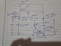
The question in post #78 was about the possibility of there being a mechanical shorted circuit connection and not about any transistor failure or breakdown. Mechanical short circuits are possible with many heat sink installation arrangements and certainly will cause problems. They are totally separate from transistor operation.
THAT is what the comment was about.
 

MrAl

Joined Jun 17, 2014
13,720
Sir,

When there is a short between Collector and emitter of Power transistor 2N3055, I can consider the transistor went to breakdown?
For sure, but how are you measuring the short. If you use an Ohm meter and it shows very low like near zero (0.1 Ohms or something) then it's blown.
 

MisterBill2

Joined Jan 23, 2018
27,679
If the resistance is the same in both directions, THEN the transistor is failed. An OK transistor can act like a diode, low forward resistance, higher reverse resistance. A mechanical short circuit will also read the same in both directions.
 

Thread Starter

ommsiva

Joined Mar 13, 2024
52
If the resistance is the same in both directions, THEN the transistor is failed. An OK transistor can act like a diode, low forward resistance, higher reverse resistance. A mechanical short circuit will also read the same in both directions.
Sir,

Instead of voltage regulator , can we use TDA2050 opamp used for audio amplifier application, since it can source 5A current and it has protection towards short circuit ?

why designers wont use this audio opamp for designing regulated power supplies?
 

MrAl

Joined Jun 17, 2014
13,720
Sir,

Instead of voltage regulator , can we use TDA2050 opamp used for audio amplifier application, since it can source 5A current and it has protection towards short circuit ?

why designers wont use this audio opamp for designing regulated power supplies?
Hi,

I could guess. Although you could do it I'm sure, it's probably not fast enough for all applications.
I did a design for a simple DC power supply where I wanted to be able to adjust the output accurately to the millivolt. I started out using an LM358 and the power supply worked ok, but I wanted faster response to a current fault, so I wanted to go to a faster op amp with 10x slew rate.
So sometimes you just need more speed. Audio stuff isn't usually made for speed it's made to work in the audio frequencies which is usually limited to around 20kHz.
It is true though you could do it, and it may even work out good enough for your purposes.
 

MisterBill2

Joined Jan 23, 2018
27,679
Sir,

Instead of voltage regulator , can we use TDA2050 opamp used for audio amplifier application, since it can source 5A current and it has protection towards short circuit ?

why designers wont use this audio opamp for designing regulated power supplies?
Aside from the response speed, which certainly matters in many applications, the other concerns are power handling and cost, which both matter in most applications.
An audio amplifier is delivering AC only, and usually at a constantly varying amplitude. So that 5-amp IC iis only passing 5-amp peaks with a lower average value. That means less heat generated than in a DC application.
The other consideration is cost, both of the device and the needed heat sink. Audio amplifiers need to be more linear than voltage regulators and that increases the cost. So the price for performance is not the same, audio devices for a given power level cost more.
 

Thread Starter

ommsiva

Joined Mar 13, 2024
52
Aside from the response speed, which certainly matters in many applications, the other concerns are power handling and cost, which both matter in most applications.
An audio amplifier is delivering AC only, and usually at a constantly varying amplitude. So that 5-amp IC iis only passing 5-amp peaks with a lower average value. That means less heat generated than in a DC application.
The other consideration is cost, both of the device and the needed heat sink. Audio amplifiers need to be more linear than voltage regulators and that increases the cost. So the price for performance is not the same, audio devices for a given power level cost more.
Sir,

LM338 regulator can provide 5Amp output, but it does not provide short circuit protection.

how to make short circuit protection with LM338?

when difference in voltage between input and output is more than 30, and if there is short at output then LM338 will go to breakdown.
 

MrAl

Joined Jun 17, 2014
13,720
Sir,

LM338 regulator can provide 5Amp output, but it does not provide short circuit protection.

how to make short circuit protection with LM338?

when difference in voltage between input and output is more than 30, and if there is short at output then LM338 will go to breakdown.
You have to add current measurement and feedback. This can often be done with a transistor and some resistors, but it's a current feedback that is just for protection not for accurate output current adjustment.
 

Thread Starter

ommsiva

Joined Mar 13, 2024
52
You have to add current measurement and feedback. This can often be done with a transistor and some resistors, but it's a current feedback that is just for protection not for accurate output current adjustment.
Sir,

I got this circuit in net, I donot Know the terms cut, load.

how this circuit is going to work during short circuit condition?
 

Attachments

Last edited:

MisterBill2

Joined Jan 23, 2018
27,679
Sir,

Whether we have some other circuits for short circuit protection of lm338.

Thank you.
OK, I am guessing that the reference ti "CUT" and"LOAD" reply to the two momentary switches in the circuit schematic drawing in post #91. Certainly those terms are a bit nebulous in the context of the circuit, although the function is fairly obvious.
The "CUT" switch function is to manually trigger the over-current protection system to remove the positive voltage feed to the regulator circuit.
The "LOAD" switch function is to reset the over-current protection system to apply the positive voltage supply to the regulator circuit. It suffers from the design flaw that it will allow the continued application of power even under an extreme overload condition, as long as the switch is operated.

So the corrected tags would be "Overload Protection Trip" and "Overload Protection Reset".
 

Thread Starter

ommsiva

Joined Mar 13, 2024
52
OK, I am guessing that the reference ti "CUT" and"LOAD" reply to the two momentary switches in the circuit schematic drawing in post #91. Certainly those terms are a bit nebulous in the context of the circuit, although the function is fairly obvious.
The "CUT" switch function is to manually trigger the over-current protection system to remove the positive voltage feed to the regulator circuit.
The "LOAD" switch function is to reset the over-current protection system to apply the positive voltage supply to the regulator circuit. It suffers from the design flaw that it will allow the continued application of power even under an extreme overload condition, as long as the switch is operated.

So the corrected tags would be "Overload Protection Trip" and "Overload Protection Reset".
Sir,

I found this circuit on web, whether this will give successful result.

Attached the circuit for reference.
 

Attachments

MisterBill2

Joined Jan 23, 2018
27,679
While I do not see any terribly obvious errors, I did not go thru any calculations to verify that all of the values are correct. And I remind the TS and all others that in most switcher regulators every connection and conductor are components that affect the performance and efficiency of the assembly. What I mean by that is that even iff one built version meets every requirement that is no assurance that a different assembly of the same components will function satisfactorily.
 

Thread Starter

ommsiva

Joined Mar 13, 2024
52
While I do not see any terribly obvious errors, I did not go thru any calculations to verify that all of the values are correct. And I remind the TS and all others that in most switcher regulators every connection and conductor are components that affect the performance and efficiency of the assembly. What I mean by that is that even iff one built version meets every requirement that is no assurance that a different assembly of the same components will function satisfactorily.
Sir,

Check this circuit and comment on the design.
1714231786647.png1714231786647.png
 

Attachments

Last edited by a moderator:

MisterBill2

Joined Jan 23, 2018
27,679
The design circuit is OK, the resistor values seem reasonable. But a big problem is that the 0.1 mfd capacitors on the LM317 regulator are missing. A small but vital detail.
And while positive and negative connections are shown, there is no need for that ground symbol that is shown. The whole circuit can float very happily.
 

Thread Starter

ommsiva

Joined Mar 13, 2024
52
Sir,

Check this circuit and comment on the design.
Sir,

I found this circuit in web and calculated node voltage.

My doubt is

1)when i move the p1 pot up to top position my node voltage will be 0.79V , which is enough to turn on my internal current limiting transistor. Then why i need those parallel 0.22ohm (4 nos)?

2)which will be the negative terminal of power supply? either Right end or Left end(where filter capacitor were connected) of current sensing resistors(4x 0.22 ohm resistors). What is the technique employed?

3) what will happen if there is no 4x0.22 ohm resistor?

Thank you
 

Attachments

Last edited:

Thread Starter

ommsiva

Joined Mar 13, 2024
52
Sir,

I found this circuit in web and calculated node voltage.

My doubt is

1)when i move the p1 pot up to top position my node voltage will be 0.79V , which is enough to turn on my internal current limiting transistor. Then why i need those parallel 0.22ohm (4 nos)?

2)which will be the negative terminal of power supply? either Right end or Left end(where filter capacitor were connected) of current sensing resistors(4x 0.22 ohm resistors). What is the technique employed?

3) what will happen if there is no 4x0.22 ohm resistor?

Thank you
Hello All,

I started constructing prototype of the below circuit, But 68ohm,2Watts resistance went to breakdown.
again i changed to 470ohm,2Watts , again it started smoking.


I also changed the MJE2955, but 470 ohm started smoking, What is the problem in the circuit?

How to find my transistor has went to breakdown?

Thank you all.
 

Attachments

MisterBill2

Joined Jan 23, 2018
27,679
Sir,

I found this circuit in web and calculated node voltage.

My doubt is

1)when i move the p1 pot up to top position mfot the current control y node voltage will be 0.79V , which is enough to turn on my internal current limiting transistor. Then why i need those parallel 0.22ohm (4 nos)?

2)which will be the negative terminal of power supply? either Right end or Left end(where filter capacitor were connected) of current sensing resistors(4x 0.22 ohm resistors). What is the technique employed?

3) what will happen if there is no 4x0.22 ohm resistor?

Thank you
The 4 0.22 ohm resistors form the series resistance for the current limiting portion of the system. They are the current sense resistor, 0.05 ohms. If they are replaced by a direct connection there will be no current limiting or current regulation. So there may be smoke. I see some other problems as well.
NOT EVERYTHING POSTED ON THE WEB IS CORRECT!!!!
 

Audioguru again

Joined Oct 21, 2019
6,826
The old TDA2050 is discussed in this thread. But it is obsolete and is not made anymore. Maybe fake ones are available today.
The audio power amplifier is designed for momentary AC audio peaks, not continuous DC for use in a power supply.
 
Top