Facebook
 Google
 GitHub
 Linkedin
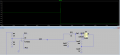
Hello , I am using the TLV3701. In the datasheet below they say that they only have GND port.
But in the simulation i put -12V instead of GND and the comprator worked fine.
Can i put +12V -12V for this type of the comparator given the datatsheet?
Thanks.
https://www.ti.com/lit/ds/symlink/tlv3701.pdf?ts=1727697533187&ref_url=https%3A%2F%2Fwww.ti.com%2Fproduct%2FTLV3701

But in the simulation i put -12V instead of GND and the comprator worked fine.
Can i put +12V -12V for this type of the comparator given the datatsheet?
Thanks.
https://www.ti.com/lit/ds/symlink/tlv3701.pdf?ts=1727697533187&ref_url=https%3A%2F%2Fwww.ti.com%2Fproduct%2FTLV3701