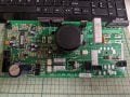
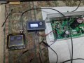
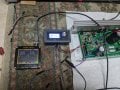
MC2100 Rev B - Treadmill Runs for a couple second then stops

MaxHeadRoom

Joined Jul 18, 2013
30,772
Thats the most common items.
DB1 = GBJ2506-F , Digikey has 23,000 in stock.
I have also picked up the 8 pin header for HD2 No. 3-643813-8
 

besligar

Joined Mar 9, 2023
28
Thats the most common items.
DB1 = GBJ2506-F , Digikey has 23,000 in stock.
I have also picked up the 8 pin header for HD2 No. 3-643813-8
Thanks! I got looking around with their filters and came up with GSIB2560-E3/45GI-ND but it only had forward voltage of 1.0, your number has the forward voltage of 1.05 the original specs so that's great, course maybe that doesn't even make a difference here. Also it's half the price.
 

besligar

Joined Mar 9, 2023
28
I decided to do a little troubleshooting before placing my order in case I need any thing else.

A scope on the PWM pin HD2-P4 when turning on the machine shows no signal.
Issue 1MPH command and get the full PWM signal, which remains after the motor surge and motor shutdown.

Move scope to Micro Pin 8 and fire up the machine, no signal.
Issue a 1MPH command and on a few attempts I can see a square wave fly by on the scope, and then nothing.

So, it looks like the micro issues the first command which trys to start the motor and then the micro stops issuing any commands even though the console is still sending them.

My take from this is hopefully the micro works (will the initial surge come if it doesn't work?)

The original suspects still apply as far as components I think, I'm assuming when one isn't working right the micro learns this from one of the pins feeding back to it and stops issuing the run stream on pin8.

All that said, does anyone have suggestions as to where to look and how to test?

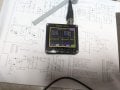
I'm attaching the scope screen of the PWM signal, for those who are wondering about this aspect of the board. I'd also like to point out that the scope used is less than $60.00 on amazon and works amazing for any one thinking about one or didn't know about them. I have an old Hitachi V212 but this thing locks on to any signal automatically for you, quite impressive for the price and the size makes it so convenient.

If I ever get the board working I'll post a picture of the micro pin 8 signal when it's functioning.
 

Attachments

MaxHeadRoom

Joined Jul 18, 2013
30,772
I would assume what is happening is that when the move command is issued, the motor starts then goes into overspeed and the micro senses this and shuts down.
Do you have any way of using a 20Hz PWM into the HD2 socket?
I have one of those types of small portable 'scope's and they do a good job for general work, especially where isolation is needed.
 

besligar

Joined Mar 9, 2023
28
I would assume what is happening is that when the move command is issued, the motor starts then goes into overspeed and the micro senses this and shuts down.
Do you have any way of using a 20Hz PWM into the HD2 socket?
I have one of those types of small portable 'scope's and they do a good job for general work, especially where isolation is needed.
I do have the pulse generator and have used it to make the machine do the initial surge. Thing is I have to start the TM with the generator on 0% duty cycle and as soon as I move to 1% the surge takes place and that is it.

I've seen reference to the MOV earlier in this thread and I'm not sure what that is. I see MOV in the upper left hand corner of the schematic and there is a MOV1 on the board that looks like a capacitor. Is there a digikey number for this and could it be the problem? Does it have to do with what you're referencing as the move command?
 

MaxHeadRoom

Joined Jul 18, 2013
30,772
The MOV shown on the schematic is just there for mains noise suppression, they either short, (self destruct) or go open with no effect on the circuit.
The Mosfet driver, MIC4227 may also be suspect, if the Mosfet it is driven by has gone faulty.
 
Last edited:

besligar

Joined Mar 9, 2023
28
The MOV shown on the schematic is just there for mains noise suppression, they either short, (self destruct) or go open with no effect on the circuit.
The Mosfet driver, MEC4227 may also be suspect, if the Mosfet it is driven by has gone faulty.
Ok, thanks for the MOV info. I have the U5 - MIC4427 on my list. I see there is a typo in the schematic on this but it appears most know about it as I seem them referencing the 4427. Some will be confused by the 4227 but searching will straighten them out.
 
Ok, thanks for the MOV info. I have the U5 - MIC4427 on my list. I see there is a typo in the schematic on this but it appears most know about it as I seem them referencing the 4427. Some will be confused by the 4227 but searching will straighten them out.
Can you post a picture of your PWM external driver, and set up. My treadmill set up was doing the same thing, and when I drove it with an external PWM signal generator from Amazon into HD2 no more issue.
 

besligar

Joined Mar 9, 2023
28
Can you post a picture of your PWM external driver, and set up. My treadmill set up was doing the same thing, and when I drove it with an external PWM signal generator from Amazon into HD2 no more issue.
I took a video but it's too big to send. Basically from 0% any movement starts the surge. Go back to 0% and move it again and I get the surge again. Same as the console.
 

Attachments

besligar

Joined Mar 9, 2023
28
In anticipation of possibly needing them, is there a cross reference to Digi-Key for the following?
U4 - MOC3052
Q5 - 2N4401 - will 2n2222 or 3904 work here?
Q6 - 2N4403 - this one has TA or TF or BU for options, will any one work?
Also my board has a Q3 & Q4, value Q1257. They don't appear on the schematic that I can find. In the micro pin list they refer to Q3 twice but it is actually Q6. Googling the number points to alternistor triacs.
Max, does this match any of your boards? Any experience with Q3 and Q4?
 

Attachments

besligar

Joined Mar 9, 2023
28
Digikey show either stock or has a sub for all , the Q3 Q4 is CTB08 for the incline motor.
If it's for the incline I won't worry about it. That's probably why it's not on the schematic. Do you have numbers for the U4 - MOC 3052 or the Q6 - 4403?

Thanks Max, have an order on the way but worry the problem is elsewhere from the heatsink components so just trying to make sure of what I can get if I need it. A lot of time...and now money invested in this. I intend to get it going, one way or another...
 

besligar

Joined Mar 9, 2023
28
Any one know of a reason to not put sockets in for U4 and U5? I have spares on the way in case I need them and would like to have sockets there. Might be good to have for troubleshooting as well.
 

kmkurada

Joined Mar 20, 2023
2
i have DK07-A01 DK10-A01 TREADMILL CONTROLLER BH G6442 G6446 TREADMILL DRIVER BOARD WHICH IS NOT WORKING I HAVE CHECKED AND REPLACED FAULTY MOSFET BUT WHEN I FIXED TO THE TREADMILL AND PRESS START BUTTON DISPLAY COMING BUT MOTOR IS NOT RUNNING SHOWING ERROR 1 AFTER SOME TIME. I HAVE CHECKED SENSOR IT IS GOOD. I CAN'T FIND THE SOLUTION CAN ANYBODY TELL ME HOW TO SOLVE THIS PROBLEM.
 

MaxHeadRoom

Joined Jul 18, 2013
30,772
I CAN'T FIND THE SOLUTION CAN ANYBODY TELL ME HOW TO SOLVE THIS PROBLEM.
Unfortunately, unless someone has reverse-engineered this controller and drawn a schematic it is is usually a case of tracing the circuit, most of these controllers , it is best to eliminate the console by trouble shooting on the bench using just the motor and control board.
 

kmkurada

Joined Mar 20, 2023
2
Unfortunately, unless someone has reverse-engineered this controller and drawn a schematic it is is usually a case of tracing the circuit, most of these controllers , it is best to eliminate the console by trouble shooting on the bench using just the motor and control board.
sir can you explain how?
 

MaxHeadRoom

Joined Jul 18, 2013
30,772
I am not familiar with that particular board, most modern ones use a form of PWM command signal from the console, if this is the case, you would need to simulate this signal in order to bench test.
 

besligar

Joined Mar 9, 2023
28
In summary for future visitors:

In looking to use a DC motor controller board with Mach3 I ended up acquiring a mal-functioning MC-2100 Rev B (thru-hole variety). So I wanted to get this board working first in the treadmill configuration and then get a PWM module to talk to it.

Powering up the treadmill, everything came on and worked except when you executed a speed button there was an initial motor surge and then nothing. Everything was still on but no motor running. You could hit stop and hit a speed button again and get the motor surge again. The red led would never go off except flickering during power up.

In the end I believe the only bad component was the Q2 Mosfet. Not knowing what was wrong I ordered a bunch of parts to cover all bases, based on what I had learned so far in this thread. I replaced Q2, Q1, DB1, U5 and C5 all at once and the board worked. Testing the components out of circuit only the Mosfet was bad. Even C5 measured a little better than the new one I put in.

Once it was running I confirmed it didn’t need speed sense (tach input) for the board to run, by unplugging the sensor, which meant I could work with the motor stand-alone now. When I started all this I thought the board wouldn’t run without tach input so I set the motor, flywheel, roller and sensor back in the frame.

Next was to get the PWM module to work and get rid of the big console. Using 20 Hz and 0 to 85% duty cycle, power for the PWM module from the INS header and ground and pulse from the module to HDR2. I couldn’t get a response. No motor movement and red led always on.

Then I came across Terrys_Dual_555_MC_2100_Driver_Circuit.pdf and on page 4 found the answer. I put a 330 ohm resistor in line with the pulse signal to the MC2100 and it fired right up. I have very accurate control from about 6% up to around 85% duty cycle. If you are above 0% duty cycle when you start the controller you have to go back to 0% and then forward before the motor and led respond. The easy workaround on this is a momentary button that interrupts power to the PWM module while you turn the board on. Then when you release the button the controller will ramp to the preset speed on the PWM module.

It appears some people are getting this to work without the resistor which would create the confusion of them actually working or not. At any rate, if you’re going down this path and not having any luck, read his article and try a resistor.

I never would have gotten this far without the resources and friendly help of this board, thanks for the great help!

Of course, always putting the cart before the horse, I now have a great functioning MC2100 responding to PWM at 20Hz. I put a scope on my Mach3 PWM output and it appears to be 200Hz. Think I’m going to need something in between….

Below is the Digi-Key parts numbers I cobbled together, most started with Max but I had to pick alternatives in some cases so be aware…also, the R32 here is a 5W, original is 1W. As well, I thought I ordered U4 as through hole but came as surface mount, didn't need it though.
 

Attachments

Top