MC2100 Rev B - Treadmill Runs for a couple second then stops

JayFET

Joined Oct 16, 2022
2
At least 16 years old. Maybe older. It wasn't used a lot though.

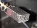
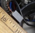
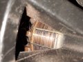
The brushes seem to have good length but I do see fine scratch lines. And I see some dark spots on the metal plates on the commutator which has me wondering could that be causing moments of high resistance and an increase in current draw? I don't see any stray materials bridging the gaps between plates. I didn't notice carbon dust but I do see metal particles on the plastic housing.

Unfortunately I'm out of mosfets so I can't do any more testing. If I place an order for more, I'm wondering if I should replace anything else. Given the age do you think C5 could be operating poorly and not filtering well enough or does this seem like only the motor that's at fault?
 

Attachments

Hashamoto

Joined Feb 13, 2023
2
I love this conversation. I am grandpa so I as repairing the daughters treadmill with the same problem. Starts then stops. Son in law fell when riding it, he is 300#. I pulled the board, all looks good. I bought the test device but have not used it yet, I expect the "reed might be a problem so I will look for something there. Any other sequence I should follow? The tech came out and did not have any idea of what was wrong so they called me because I am retired and cheap..... :0
 

MaxHeadRoom

Joined Jul 18, 2013
30,772
If this is a MC2100 version, you can test the board and the motor on the bench if you have the 20Hz PWM tester to plug into the HD2 socket.
 
Max,
If the AC power goes off ie the displays go blank/blue and then comes back on by itself, isn’t that caused by the MOV activating? If the controller senses over current, wouldn’t it go into fail safe mode?
 

besligar

Joined Mar 9, 2023
28
The LED should be lit with power applied to the board and nothing else plugged in, I test them stand alone with a 20Hz PWM generator I have made up with some custom boards to provide PWM and stop start into the HD2 socket.
Max, I'm playing with a PWM signal generator on Header2 Pin4 using 20Hz, Duty cycle 13% to 85% to try and run without the console, you mention custom boards and stop start into the H2, can you elaborate? Or provide a link to your work? Been following your input in this thread, Thanks!
 

MaxHeadRoom

Joined Jul 18, 2013
30,772
The input is into an Opto isolator, but the input resister is very low, 22Ω and usually requires a resistor in series, dependent on the voltage used.
The ones I put together have a pot to control speed and plug into the HD2 header. Embedded Picmicro as a control source.
There is a terminal strip in order to connect two P.B.;s for stop start.
Boards measure 50mm x 50mm.
 

besligar

Joined Mar 9, 2023
28
The input is into an Opto isolator, but the input resister is very low, 22Ω and usually requires a resistor in series, dependent on the voltage used.
The ones I put together have a pot to control speed and plug into the HD2 header. Embedded Picmicro as a control source.
There is a terminal strip in order to connect two P.B.;s for stop start.
Boards measure 50mm x 50mm.
So are these boards that you sell only, or have you made the schematic and code available somewhere?

What I get from your comment is that just hooking a pulse generator to the blue wire with the right PWM range won't work as something has to add the start stop commands into the mix?
 
So are these boards that you sell only, or have you made the schematic and code available somewhere?

What I get from your comment is that just hooking a pulse generator to the blue wire with the right PWM range won't work as something has to add the start stop commands into the mix?
The motor should run if you put in a 20 Hz PWM signal with no additional inputs as long as the board has power
 

MaxHeadRoom

Joined Jul 18, 2013
30,772
So are these boards that you sell only, or have you made the schematic and code available somewhere?
What I get from your comment is that just hooking a pulse generator to the blue wire with the right PWM range won't work as something has to add the start stop commands into the mix?
I generally sell them for what it cost me to design and put together, ~US$25.00 + P/P I include the pot, but you need a couple of P.B.s.
And as mentioned, you do not require the P.B.'s to run, I included them for those that use the motor/MC2100 for a machine tool etc.
 

besligar

Joined Mar 9, 2023
28
I've put the cart before the horse guys, turns out I have a faulty board to fix first and didn't know it.

The unit was cheap because it had stopped working. The project was to get the motor and controller out of it to use in a mill with mach3 pwm control.

The treadmill powers up but when command issued the belt would start and stop immediately. Display still fully functional. I assumed the tach sensor. When I dismantled the unit the sensor was out of place so I made the assumption I had a working board.

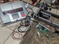
My setup was the console, MC-2100 Rev B board and motor for testing.
Unfortunately it did the same thing, motor surge and then off. Thought I better add tach input so taped a magnet to the motor shaft and set the sensor near it. I still got the same results but now when hitting 1mph I got the surge and a speed read of 1.6 mph before shutting down.

With the motor pulley to roller ratio being approximately 1:2 and the magnet on the motor instead of the roller the tach input was approximately doubled so I figured that might be the problem. So I mounted the roller and motor back in the bottom front frame along with the sensor so tach input to the control board and console is as it would be in the treadmill. The problem still persists so the board has to have a fault.

Not quite sure what to do next I started playing with the amazon pulse generator and no console. Basically what I found was if duty cycle was 0 to start I could produce the same result as the console by moving from 0 to 1% with the dial I would get a brief surge. It would take a reset with the generator on 0% first to repeat the surge by turing the dial and increasing %.

My focus now is to try to find the board fault and fix it. I have the schematic from earlier in the thread , any thoughts on where to start?
 

Attachments

MaxHeadRoom

Joined Jul 18, 2013
30,772
The normal built in PWM is read by the processor and ramped up, for e.g., when you use a stop start by cutting off the PWM signal, when restarted at the same setting, the processor goes into a ramp up sequence, i.e. no sudden zero to high rpms.
No tach or FB used.
On the actual T.M., the belt or motor tach is fed up to the console processor for speed control through the HD2 socket.
IOW, It bypasses the MC2100 board.
Also if using for machine control, it is usual to remove the flywheel. Mach will also output the PWM as low as 20Hz IIRC, so you do not require an analogue convertor.
 

besligar

Joined Mar 9, 2023
28
The normal built in PWM is read by the processor and ramped up, for e.g., when you use a stop start by cutting off the PWM signal, when restarted at the same setting, the processor goes into a ramp up sequence, i.e. no sudden zero to high rpms.
No tach or FB used.
On the actual T.M., the belt or motor tach is fed up to the console processor for speed control through the HD2 socket.
IOW, It bypasses the MC2100 board.
Also if using for machine control, it is usual to remove the flywheel. Mach will also output the PWM as low as 20Hz IIRC, so you do not require an analogue convertor.
That right there answers so many questions! I thought the micro required feedback from either the sensor or the console to proceed with issuing pwm command because of safety. Instead the micro accepts whatever pwm commands it receives and forwards it in a ramping fashion without any feedback. This is perfect for Mach3 use.

Also I can go back to just the motor and board on the bench without the flywheel.

Course I have the little hiccup of getting the board fixed.

The light appears to be on solid but it is possible there is a little flicker when command is issued and motor surges, but for the most part stays on. Because there is a surge and shutdown wouldn't that mean the micro received it's command but the result of the micro pin 8 output causes the shutdown? Which would point to U5, Q2, D13 as suspects from earlier readings here?
 

MaxHeadRoom

Joined Jul 18, 2013
30,772
The micro use a SCR to ramp up the DC so any sudden surge can either be the SCR or the components connect to it.
In some cases the Mosfet is shorted.
The processor in the console does most of the processing, the MC2100 board itself just processes the command and ramp up.
 

besligar

Joined Mar 9, 2023
28
The micro use a SCR to ramp up the DC so any sudden surge can either be the SCR or the components connect to it.
In some cases the Mosfet is shorted.
The processor in the console does most of the processing, the MC2100 board itself just processes the command and ramp up.
I've got a Digi-Key order ready, ordering everything on the heat sink, the 4427 and R32 .01ohm. Is there a Digi Key equivalent for DB1 - D25XB 60? Can't find it using that number. Also, is there anything else would be worth picking up while making the order?

Thanks
 
Top