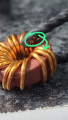
Magnetic amplifier I found in a SMPS released in 2013 (modern)

Thread Starter

kiroma

Joined Apr 30, 2014
228
Hello!
I'm attaching the file I made with Claude after putting a reversed engineered schematic (a mess to understand) for it to change the layout without changing the circuit (tidying it up).

The SMPS is model FSP350-60APN from Corsair. I got this SMPS by a ex-colleague that said I could have it if I thought I could fix it.
So far, I couldn't fix it yet, but I'm making progress, and the best part is learning brand new ideas of circuits.

Magnetic amplifiers are something in between linear regulators and switched mode converters (and also in the middle in terms of efficiency), but way more reliable, very resistant to radiation, no moving parts, no transistors (this one has a TL431, but you can do without it if you want and has a low power transistor compared to the 3V3 current).

I simulated the circuit with an estimation of value of the filtering components. The 100 mH is the saturable inductor, it has high inductance but very low current for it to saturate (1 mA). The 5 ohm resistor in series with the inductor is to mitigate ringing between the capacitors and the inductor. It's important to have a good capacitance at the output to prevent oscillations. The 180 nF in series with 1 kΩ are there to lower ripple on the output.
Falstad Circuit Simulator - Magnetic Amplifier circuit of SMPS FSP350-60APN

I found that if you take the emitter of the PNP transistor and put it to the output voltage node, it requires less current to dessaturate the inductor, with seemingly no drawbacks. It goes from ~58 mW avg to ~18 mW avg on the 4.7 ohm resistor.

Also, for those who are unfamiliar (as I was few days ago, even after more than a decade studying electronics):
Explanation of how magnetic amplifiers work

This is the image I found on the web and used Claude to generate the PDF:
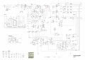
bb25603a-4257-45f8-9483-5170e4f991e0.jpg

TL;DR: this is a post to show something cool that I found and could simulate, no need to help me with something, but if you think you can contribute with our learning, go on, I appreciate.
 

Attachments

Last edited:

Thread Starter

kiroma

Joined Apr 30, 2014
228
To those who will encounter this thread in the future and to those who are watching it:
Falstad Circuit Simulator does not have a hysteresis effect on any inductor (I discovered 1 hour ago while chatting with Claude), it can saturate but it's always the same value for the same input, so the circuit isn't really working as intended, besides regulating it right. The hysteresis is important because it magnetizes the core with a magnetic retention (the remaining B field when no H field).

The best approach I'd do now is to simulate on LTSpice. I don't feel like I'll do it in the short term, so feel free to simulate and post your results here if you wish, I'd be curious what really is the waveforms and amplitudes (given the values of components).
 
Last edited:

ronsimpson

Joined Oct 7, 2019
4,823
There are a number of different types of "Mag-Amps".
I do not have the knowledge to make SPICE cores that will work. Over my head.
I have used them in TV sets (CRT monitors) to change the Horizontal Size on the fly. Also to adjust the H. Linearity dynamically.
I have used MagAmps; where there are several outputs of a power supply. One output is in the control loop, and the rest need to be regulated in their own loops.
They also adjust the resonant frequency of a LC resonant power supply.
There must be more ways of using them. Now I remember that we used the earth's field to change the saturation points of cores to make solid-state a compass.
 

schmitt trigger

Joined Jul 12, 2010
2,244
Magnetic amplifiers are fascinating devices. I found them in a mid 1990s multi output power supply used by a high end workstation.
Even back then, the core material was very expensive. It was made of a thin ribbon of exotic magnetic material wound as a toroid. I believe it was the cost what eventually caused them to be superseded by the rapidly improving Mosfets.
 

Thread Starter

kiroma

Joined Apr 30, 2014
228
I have one question.
Is it possible to use a mag amp to amplify audio without distortion?
I see that the saturation is intrinsically nonlinear, so you can't amplify linearly, right?
 

ronsimpson

Joined Oct 7, 2019
4,823
s it possible to use a mag amp to amplify audio without distortion
An op-amp (without feedback) is not linear either. Op-amps use feedback and high gain to reduce distortion. Almost any power amplifier can be used to make an audio amplifier. It is the feedback that compares the input signal to the output signal and corrects for errors.
 

Thread Starter

kiroma

Joined Apr 30, 2014
228
Magnetic amplifiers are fascinating devices. I found them in a mid 1990s multi output power supply used by a high end workstation.
Even back then, the core material was very expensive. It was made of a thin ribbon of exotic magnetic material wound as a toroid. I believe it was the cost what eventually caused them to be superseded by the rapidly improving Mosfets.
Maybe it was this core?
 

Thread Starter

kiroma

Joined Apr 30, 2014
228
An op-amp (without feedback) is not linear either. Op-amps use feedback and high gain to reduce distortion. Almost any power amplifier can be used to make an audio amplifier. It is the feedback that compares the input signal to the output signal and corrects for errors.
I totally forgot about how negative feedback is so helpful.
 

Thread Starter

kiroma

Joined Apr 30, 2014
228
Just came here to explain the solution. Last weekend I found out when I cut the heat-shrink covering the mag amp inductor that the heat-shrink on each inductor leads, one of them melted a bit (probably because of too much current there) and it was just being isolated by the enamel between the 2 leads, basically. I suspect that at that high temperature the enamel was not solid to isolate and it conducted. So the 5 V at somewhat high duty went through the 3V3, causing the filter capacitor to bloat, but not enough to damage it (I tested for capacitance, just the ESR is a bit higher), so the OVP triggered. Nevertheless, I changed it for a good one. After separating the short-circuit, I tested it about 3 times and it worked normally.
Photo to see what I'm talking about. The terminals are made of 3 wires in parallel, so that arrow is the first turn of the mag amp inductor of the lower lead.
This gave me a very good amount and duration of dopamine, as I did for the challenge of doing it, not for money.
 

Attachments

Last edited:

MisterBill2

Joined Jan 23, 2018
28,353
I examined that circuit and while i saw transformers I did not see what I would call a magnetic amplifier. So what part of the circuits shown is thought to be a "MAG AMP"???
 

Thread Starter

kiroma

Joined Apr 30, 2014
228
The L3 inductor, that's in series to the rectification by BD2 and filtering to the 3V3 output.
I don't have for certain that magnetic amplifier is the correct term for it, but Claude keeps calling it the mag amp. For me it's like the circuit is a mag amp, not just the inductor.
 

MisterBill2

Joined Jan 23, 2018
28,353
The L3 inductor, that's in series to the rectification by BD2 and filtering to the 3V3 output.
I don't have for certain that magnetic amplifier is the correct term for it, but Claude keeps calling it the mag amp. For me it's like the circuit is a mag amp, not just the inductor.
Fundamentally ANY mag-amp must have at least two windings, so that one can vary the magnetization affecting the impedance of the other winding. THAT MEANS that a single inductor can not be a "mag-amp". What is shown would be called a "choke" or a "filter choke", intended to resist rapid changes in the DC current. Almost without exception, an amplifier has separate inputs and outputs. The possible exceptions would be "tunnel diodes", and other negative resistance devices.

It seems that your information source is slightly confused.
 

Thread Starter

kiroma

Joined Apr 30, 2014
228
Fundamentally ANY mag-amp must have at least two windings, so that one can vary the magnetization affecting the impedance of the other winding. THAT MEANS that a single inductor can not be a "mag-amp". What is shown would be called a "choke" or a "filter choke", intended to resist rapid changes in the DC current. Almost without exception, an amplifier has separate inputs and outputs. The possible exceptions would be "tunnel diodes", and other negative resistance devices.

It seems that your information source is slightly confused.
I think you're right in saying it should have 2 windings to be considered a mag amp, but this inductor is not a regular one.
Because Claude said it was a mag amp and because I read on wikipedia "Semiconductor-based solid-state switches have largely superseded them, though recently there has been some regained interest in using mag amps in compact and reliable switching power supplies. PC ATX power supplies often use mag amps for secondary side voltage regulation.", which fits very well what I encontered.
This inductor have high inductance, low saturation current, and square B-H curve, which is suitable to act like a switching element. It passes low current until saturation, then high current until the circuit near it reset its magnetic core.
So I think that a choke or filter doesn't fit the description too.
 
Top