Facebook
 Google
 GitHub
 Linkedin

Hello!
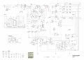
I'm attaching the file I made with Claude after putting a reversed engineered schematic (a mess to understand) for it to change the layout without changing the circuit (tidying it up).
The SMPS is model FSP350-60APN from Corsair. I got this SMPS by a ex-colleague that said I could have it if I thought I could fix it.
So far, I couldn't fix it yet, but I'm making progress, and the best part is learning brand new ideas of circuits.
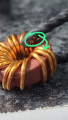
Magnetic amplifiers are something in between linear regulators and switched mode converters (and also in the middle in terms of efficiency), but way more reliable, very resistant to radiation, no moving parts, no transistors (this one has a TL431, but you can do without it if you want and has a low power transistor compared to the 3V3 current).
I simulated the circuit with an estimation of value of the filtering components. The 100 mH is the saturable inductor, it has high inductance but very low current for it to saturate (1 mA). The 5 ohm resistor in series with the inductor is to mitigate ringing between the capacitors and the inductor. It's important to have a good capacitance at the output to prevent oscillations. The 180 nF in series with 1 kΩ are there to lower ripple on the output.
Falstad Circuit Simulator - Magnetic Amplifier circuit of SMPS FSP350-60APN
I found that if you take the emitter of the PNP transistor and put it to the output voltage node, it requires less current to dessaturate the inductor, with seemingly no drawbacks. It goes from ~58 mW avg to ~18 mW avg on the 4.7 ohm resistor.
Also, for those who are unfamiliar (as I was few days ago, even after more than a decade studying electronics):
Explanation of how magnetic amplifiers work
This is the image I found on the web and used Claude to generate the PDF:
TL;DR: this is a post to show something cool that I found and could simulate, no need to help me with something, but if you think you can contribute with our learning, go on, I appreciate.
I'm attaching the file I made with Claude after putting a reversed engineered schematic (a mess to understand) for it to change the layout without changing the circuit (tidying it up).
The SMPS is model FSP350-60APN from Corsair. I got this SMPS by a ex-colleague that said I could have it if I thought I could fix it.
So far, I couldn't fix it yet, but I'm making progress, and the best part is learning brand new ideas of circuits.
Magnetic amplifiers are something in between linear regulators and switched mode converters (and also in the middle in terms of efficiency), but way more reliable, very resistant to radiation, no moving parts, no transistors (this one has a TL431, but you can do without it if you want and has a low power transistor compared to the 3V3 current).
I simulated the circuit with an estimation of value of the filtering components. The 100 mH is the saturable inductor, it has high inductance but very low current for it to saturate (1 mA). The 5 ohm resistor in series with the inductor is to mitigate ringing between the capacitors and the inductor. It's important to have a good capacitance at the output to prevent oscillations. The 180 nF in series with 1 kΩ are there to lower ripple on the output.
Falstad Circuit Simulator - Magnetic Amplifier circuit of SMPS FSP350-60APN
I found that if you take the emitter of the PNP transistor and put it to the output voltage node, it requires less current to dessaturate the inductor, with seemingly no drawbacks. It goes from ~58 mW avg to ~18 mW avg on the 4.7 ohm resistor.
Also, for those who are unfamiliar (as I was few days ago, even after more than a decade studying electronics):
Explanation of how magnetic amplifiers work
This is the image I found on the web and used Claude to generate the PDF:
TL;DR: this is a post to show something cool that I found and could simulate, no need to help me with something, but if you think you can contribute with our learning, go on, I appreciate.
Attachments
-
131.7 KB Views: 10
Last edited: