LTSpice - How to add new Diode

ericgibbs

Joined Jan 29, 2010
21,469
Is there any online simulator that shows me the current and voltage directions during a period? I need to understand what happens in several points of the circuit!
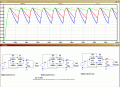
If you look at the sim plots, use the Time Xaxis and the Volts Y axis and you can see what any point of the circuit is doing.

Moving on, can you see now why I use the Vmin voltage, when I calculate the Rs value.??
 

Thread Starter

PsySc0rpi0n

Joined Mar 4, 2014
1,786
I need to say something else regarding the report I have to do.

The Iz is not 10% of the I_l... That info was not accurate. I don't know how to calculate the I_z. They give us the Zener potency of 0.5W but i don't know if i can calculate I_Z from P=V.I!
 

ericgibbs

Joined Jan 29, 2010
21,469
hi,
Using P= I*V
I = P/V = 0.5/5.6 = 89mA, which is the specified maximum current.

I would use only ~10% of that value for that circuit say, 9mA

So you now know the Vmin from Vc, which is ~6.5V
You also know at 5.6V across the 330R thats Irl = 17mA

Thats a total Irs of 26mA.

So calculate Rs = [Vmin - Vz]/ Irs = .........

You should also calculate the maximum value of Iz at Vmax to ensure that P for the zener is less than 0.5Watts.

OK.?

EDIT:
After you have recalculated the Rs value, run a LTS simulation to check your values.
You will see that the value of Vmin has changed due to the change in the Cap and Rs Time Constant.
 
Last edited:

Thread Starter

PsySc0rpi0n

Joined Mar 4, 2014
1,786
But you saying that Vmin is 6.5V, based on what? I'm sorry to be changing what we have agreed but i really need to sort this out becase if I don't send this today to my teacher, he will kill me, and I'll have a penalty beacuse i'm really out of schedule to send him the report!
 

Thread Starter

PsySc0rpi0n

Joined Mar 4, 2014
1,786
Looks like I was misinterpreting the problem...

They give us the Zener power which is 0.5W.
They say us that we have to consider the Vi_min e Vi_max, Iout_min, Iout_max and that the Rs must be such a value that makes the zener to work within the limits of Iz_min = 10% of Iz_MAX and Iz_max = 90% of Iz_MAX.

So, Rs_max would be for R_load = 330Ω and Rs_min would be for R_load = 1MΩ

Iz_MAX should be the one calculated via P=V.I.

So, following this intel I would do the follwoing:

0.5=5.6I<=>I=89.29mA

Iz_min = 8.929mA
Iz_max = 80.36mA

I_rload max= 5.6/330 = 16.97mA
I_rload min = 5.6/1E6 = 5.6μA

Then i have the formulas on the attachment given by the teacher to calculate Rs_min and Rs_max.

Then, using those formulas for Rs:

Rs_min = (6.4-5.6)/(0.0000056+0.0008929) = 44.79Ω

Rs_max = (6.4-5.6)/(0.01697+0.08036) = 8.22Ω

What you think?
 

Attachments

Last edited:

ericgibbs

Joined Jan 29, 2010
21,469
hi,
I think you have misread the question
.
They give us the Zener power which is 0.5W.

They say us that we have to consider the Vi_min e Vi_max, Iout_min, Iout_max and that the

Rs must be such a value that makes the zener to work within the limits of

Iz_min = 10% of Iz_MAX and Iz_max = 90% of Iz_MAX.

Iz_min = 8.929mA
Iz_max = 80.36mA

I would read the question as I must select the Rs resistance value that ensures that the zener current is greater than 10% , but be must less than 90% of its maximum rated rated current.

So this suggests you can select a zener current between
Iz_min = 8.929mA
Iz_max = 80.36mA

I would therefore choose say ~20mA and calculate Rs when Rload =330R

Did the tutor say that you should also calculate also using a 1Meg resistor as load in place of the 330R.???

Do you have printed copy of the actual question that you could post, something does not sound correct to me.
 
Last edited:

Thread Starter

PsySc0rpi0n

Joined Mar 4, 2014
1,786
I could post the question but everything is in Portuguese!!! I can try Google Translator :p

By now i have already sent the report to my teacher but i would like to understand it...
 

Thread Starter

PsySc0rpi0n

Joined Mar 4, 2014
1,786
Ok, my last values for Rs_max and Rs_min were Rs_min = 16.67Ω and Rs_max = 32.82Ω.

Those previous values were wrong somehow...

Did the tutor say that you should also calculate also using a 1Meg resistor as load in place of the 330R.???
Actually, the teacher already reformulated the question because it was not very correct but I'll post here a google translation of the original question:

Google Translator said:
Calculate analytically RS (figure 3) (value and power) and simulate the circuit in LTspice considering that its load can take values ​​of 1 MΩ, 1 k and 330 Ω, using the C calculated at 2.1.
Plot VRL, IRL, VRS and IRS. Comment. Consider that the Zener has a power of 0.5 W.
Consider the following model zener:
. Z5V6 model D (Is = 1.5N = Rs = .005 Cjo 185p nbv VJ = .7 = 1 bv = 5.6 IBV = 57.477E-3 Vpk = 5.6)

After teacher has been asked about what was asked in the question, he said to calculate only RS for 1MΩ and 330Ω load resistor.

So I have assumed that for 10% of Iz_max I would have the 1MΩ load resistor and for 90% of Iz_min I would have the 330Ω load resistor!
 
Last edited:

ericgibbs

Joined Jan 29, 2010
21,469
Calculate analytically RS (figure 3) (value and power)
and simulate the circuit in LTspice

considering that its load can take values ​​of 1 MΩ, 1 k and 330 Ω,


using the C calculated at 2.1.

Plot VRL, IRL, VRS and IRS.

Comment. Consider that the Zener has a power of 0.5 W.
Morning Psy

I would read the question as asking for calculations and LTS plots using a 330R resistor as a load across the zener and repeat the calculations using a 1Meg resistor as the load.

I do not see in the question any details about the recommended value of the operating current in the zener, other than its a 5.6V rated at 0.5W, which would give a maximum allowed current of 89mA.

I would choose a zener current of approx ~10% of this value, say 10mA.

You can calculate the current thru the 330R load resistor, from Vz/Rload.

Adding Iz and Iload will give the total current flowing thru Rrs [ the series resistor].

So the target Iz + Iload = 10mA + 17mA = 27mA.. at the lowest value of the ripple voltage Vc on the capacitor C1.
[ its important in a zener regulator that it remains in current conduction over the full range of any ripple voltage on Vc, if Iz drops to 0mA the regulation voltage will not be maintained ]

It would be good practice to also calculate the total current at the highest value of Vc on the capacitor, so that you can check the dissipation in the zener does not exceed 0.5Watts.

Repeat the above using a 1Meg load resistor in place of the 330R.

E

Lets know what answers the tutor gives for this question.
 

Thread Starter

PsySc0rpi0n

Joined Mar 4, 2014
1,786
...

I do not see in the question any details about the recommended value of the operating current in the zener, other than its a 5.6V rated at 0.5W, which would give a maximum allowed current of 89mA.

...

Lets know what answers the tutor gives for this question.
Yes I know about that but I sent an email to my teacher asking how would we calculate the Iz and he said that (google translated):

Google Translator said:
The choice of Rs should be made ​​considering the operating conditions of the circuit (and taking into account Vi_min Vi_max, and Iout_min Iout_max).
The two possible extreme values ​​for Rs are those which cause the current in the zener to be 10% of IZ_max and 90% of IZ_max.

I don't know if my teacher would give me the correct answer, but I can try to ask him...

These jobs must be made by us. It's not an exercise from our book or so... That's why I'm saying that I don't know if they are going to give me an exact result!


Anyway, can we keep analysing that simple circuit we was analysing??
 

ericgibbs

Joined Jan 29, 2010
21,469
OK,
I would recommend that you break down the analysis into two parts.

1. The change in the voltage on Vc when connected to a full wave bridge rectifier.
Using say a fixed value of C1 capacitance and and say 100R, 200R, 1K resistors.

This will give you a better understanding of what values of Vmax and Vmin [ ripple] appear due to the different C1 discharge Time Constant of C1 and Rload.

2.
Using a fixed DC Vsource [ a LTS Voltage source] construct the Rrs , zener and Rload circuit, using LTS and measure the Vz, Iz, Rrs, Rload currents and voltages for different values of Vsource.

E

EDIT:
This LTS asc should get you started
 

Attachments

Last edited:

Thread Starter

PsySc0rpi0n

Joined Mar 4, 2014
1,786
Nice...

Let me just look at that for a few minutes!


PS: Is it possible to change the thickness of the plotted lines in LTSpice?

Edit 1;

Is the time constant always \(\tau = R\cdot C\) for any circuit or does it depends on the circuit?
 
Last edited:

Thread Starter

PsySc0rpi0n

Joined Mar 4, 2014
1,786
I just wanted to know if the time constant formula is the same for any type of circuit or if it is R.C only for RC circuits. I know that for RL circuits, it's L/R I guess.

I understand the concept... The capacitor takes the 1st tau to charge up to 63.2% of it's full capacity. The other 4 taus will charge the remaining capacity!

Thanks for the tip on LTSpice thick lines!
 

ericgibbs

Joined Jan 29, 2010
21,469
The TC for a R/C charge/discharge is R * C

The tau' also discharges the Cap down to 0.63 of its initial peak value,, this is relevant to your bridge/C1/Rt discharge circuit.;)

Whats the next step?
 

Thread Starter

PsySc0rpi0n

Joined Mar 4, 2014
1,786
Well, I haven't done yet what you have told to me because I've been adding to the report the laboratorial part of the simulation. I think I'll do what you told me to do. Change Vin, change Rload and Cap value to check the differences between every change!
 

Thread Starter

PsySc0rpi0n

Joined Mar 4, 2014
1,786
I have already took a look in that tutorial...

I'll check it again and always that I need to know something about LTSpice... Looks really useful!
 
Top