Looking for ways to expand a design from single use to multi-use

sghioto

Joined Dec 31, 2017
8,737
The LED, which may or may not be visible from 20 feet away,
I can vouch using a super bright 5mm white LED at 20ma is easily visible at over 100ft.
I may be looking at circuit #54 incorrectly, but it seems to me that Q1102 has to be active to turn on the test lamp, so it does test the ignition circuit end to end. It does not test the continuity of the actual igniter, the other circuit does that.
OF course Q1102 must be active and it does check the continuity of the igniter. What do you mean by the "other circuit"?
I am not seeing the purpose of D1
It suppresses the reverse EMF voltage from the relay coil to protect the mosfet driver.
What are the worst case scenarios in this design?
Probably the app on the phone. Meaning have you covered all the bases.
Do you prefer the circuit in Post #54 or 58?
 
Last edited:
Thread Starter

phillipsoasis

Joined Aug 22, 2022
170
I can vouch using a super bright 5mm white LED at 20ma is easily visible at over 100ft.

OF course Q1102 must be active and it does check the continuity of the igniter. What do you mean by the "other circuit"?

It suppresses the reverse EMF voltage from the relay coil.

Probably the app on the phone. Meaning have you covered all the bases.
Do you prefer the circuit in Post #54 or 58?
Yes, 5mm LEDs can be seen from a distance outside depending on the viewing angle and the position of the sun relative to the observer. A white 5 mm LED puts out 20 lumens/watt, so at "spec" (20 mA @ 3.6V) you are looking at ~1.5 lumens. An 1157 tail light emits ~402 lumens.

The "other circuit" is the one with the Ckt_OK signal. Now I see that there is always current going through the igniter from Q2 when Q1102 is active, so the continuity of the igniter is under test when the light bulb is on or off, as long as Q1102 is active.

How do the circled diodes suppress reverse EMF from the relay? They were the focus of my earlier comments. That is the function of D1101. If the circled diodes are needed to suppress reverse EMF, then why isn't there one in circuit #58 attached to pin 1 of the relay?

Of course the software can fail, but we are not looking at the software, we are talking about hardware. I was asking about potential/possible hardware failures.
 

Attachments

crutschow

Joined Mar 14, 2008
38,670
Apollo used redundancy in many of their circuits, so you could use two relays with their contacts in series.
That way, if one contact would weld shut, there would still be another to open.
 
Last edited:

crutschow

Joined Mar 14, 2008
38,670
Without the diodes like D1 all mosfet drains are connected together.
The MOSFETs have the ignitor in series, so will not have a current path unless the MOSFET is turned on.
So how would having the ignitors connected in parallel to the relay output without diode isolation be a problem?
 

sghioto

Joined Dec 31, 2017
8,737
A beeper can be added to the LED circuit as an additional alert if a mosfet is shorted when connecting the ignitor leads.
 
Last edited:

sghioto

Joined Dec 31, 2017
8,737
The MOSFETs have the ignitor in series, so will not have a current path unless the MOSFET is turned on.
So how would having the ignitors connected in parallel to the relay output without diode isolation be a problem?
Which circuit are you referring to?
I was responding to the circuit in post #54.
 

sghioto

Joined Dec 31, 2017
8,737
It prevents current flowing through the igniter LED circuit from back feeding through all other igniters through the test lamp.
 
Last edited:

crutschow

Joined Mar 14, 2008
38,670
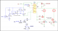
The TS has some understandable concern about the indicator LED brightness, so here is my continuity circuit modified to light an incandescent auto bulb (could also be a 1157 LED replacement) for higher brightness, instead of the small LED.
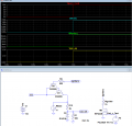
Below is the sim of the modified circuit:

The transistor is a Sziklai Pair (sometimes called a Complementary Darlington) with a 10A NPN power output transistor to provide extra current gain, and handle the much higher current of the bulb, which is now switched by the transistor output.
Otherwise it operates the same as the previous circuit with a current of about 18mA through the igniter during the test.

1730432554778.png
 
Last edited:

crutschow

Joined Mar 14, 2008
38,670
To avoid adding a different transistor part type (the 2N3055), here's the circuit driving the bulb using an igniter MOSFET:

1730470348480.png
 
Last edited:

sghioto

Joined Dec 31, 2017
8,737
Its getting better with each new modification.
:D
As I suggested before a beeper could be wired across the lamp as an audible alert. The standard procedure when at the launch pad is to touch the igniter leads together before connecting to the igniter. If there is a spark that would indicate a problem. With this system the lamp and beeper would both be active indicating a problem.
 
Last edited:

Thread Starter

phillipsoasis

Joined Aug 22, 2022
170
Its getting better with each new modification.
:D
I agree 100%

Just to recap. Looking at circuit #54

1. (post #70) The diode connected to the igniter is needed to prevent current from the incandescent test lamp from flowing (somehow) back through R6 when the test lamp is on (Q1102 is on). Is this possible?

2. (post #66) The diode connected to pin 1 of the relay is not needed.

@crutschow Thank-you for all the light bulb circuit variations and other circuits! They are extremely helpful!
@sghioto Thank you for all your great contributions!

@crutschow To respond to your comment regarding adding redundancies, I don't think this is the same situation as a spacecraft away from the earth. Any failure of the launcher can be fixed. I am more concerned about preventing a failure, or loudly advertising a failure, that could hurt a person (i.e. me!) attaching leads to an igniter or randomly cooking off a rocket before the controller (e.g. the software) tells it to fire.

I was thinking about the failure mode of MOSFETS and they fail closed a lot. If Q1102 were to fail closed (heat, usages, high current, manufacturing defect, ect.) in circuit #54, the light bulb would go on and could not be turned off. It would be very visible and obvious. In circuit #58, the green continuity LED would turn on and stay on. Should be visible and obvious when close to the launcher box unless the sun is just at the wrong angle. In both cases, there is 16 - 20 mA flowing in the igniter circuit, which is not lethal, but on the verge of dangerous (sustained muscle contractions and labored breathing). Circuit #73 would eliminate the option of not seeing the green LED in this failure mode and simplify the design a bit with just a SPDT relay and no diodes. Regarding the 16 - 20 mA current - don't touch a live circuit when in a known failure mode! #58 + #73 is a winner!

Are there other failure modes that might bite the person tinkering with the igniter?

Looking at circuit #73
If Q2 failed as a short, and the user turned on Q1102 to check continuity, would the igniter have enough current to ignite?

What would happen if M1 shorted? What if the gate shorted to the drain? What would happen to Q2 and the continuity test current to the igniter?

This whole discussion has been extremely useful!
 

sghioto

Joined Dec 31, 2017
8,737
In both cases, there is 16 - 20 mA flowing in the igniter circuit, which is not lethal, but on the verge of dangerous (sustained muscle contractions and labored breathing).
Not when the supply is only 12 volts you would feel nothing unless maybe you stuck your tongue on it. :p
 
Top