Facebook
 Google
 GitHub
 Linkedin
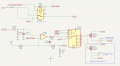
I have a design for a rocket launcher that controls one igniter. Current for the igniter is ~3-5A for about 500 msec.
Here is the igniter circuit concept:

I now need to expand the design to control up to 64 igniters. Still working out the levels (i.e. min set of igniters, average set of igniters).
Option 1 - replicate the cicuit above for each igniter. Seems to be too expensive in parts (~$8-$10) and pcb real estate (relays take up a lot of room).
Option 2 - use a high side switch (eg TPS27SA08) for each igniter, and just one relay, DAC, Op-amp, and MOSFET for all igniters

Each TPS27SA08 costs about $3 in single unit quantities. A more cost effective solution, but still expensive when looking at 64 igniters. The design does not scale that well given all the GPIO pins needed, too There are high side switches that can drive up to 4 loads, so that helps with the cost and number of GPIO pins. TI has a dual high side current switch that is controlled from an SPI bus (TPS2HCS10-Q1) which helps with pcb space as well as GPIO pins needed, but it is not in production yet.
I have been looking at a way to just replicate the MOSFET for each igniter using an analog multiplexer such as a CD4051B (~$0.40), but I can't figure out how to connect the igniters to the different MOSFETs without replicating the relay, which defeats the purpose of lower cost and less pcb real estate.
I thought I would ask the brain trust here if there is a different design that scales a little better than these two options.
Here is the igniter circuit concept:
I now need to expand the design to control up to 64 igniters. Still working out the levels (i.e. min set of igniters, average set of igniters).
Option 1 - replicate the cicuit above for each igniter. Seems to be too expensive in parts (~$8-$10) and pcb real estate (relays take up a lot of room).
Option 2 - use a high side switch (eg TPS27SA08) for each igniter, and just one relay, DAC, Op-amp, and MOSFET for all igniters
Each TPS27SA08 costs about $3 in single unit quantities. A more cost effective solution, but still expensive when looking at 64 igniters. The design does not scale that well given all the GPIO pins needed, too There are high side switches that can drive up to 4 loads, so that helps with the cost and number of GPIO pins. TI has a dual high side current switch that is controlled from an SPI bus (TPS2HCS10-Q1) which helps with pcb space as well as GPIO pins needed, but it is not in production yet.
I have been looking at a way to just replicate the MOSFET for each igniter using an analog multiplexer such as a CD4051B (~$0.40), but I can't figure out how to connect the igniters to the different MOSFETs without replicating the relay, which defeats the purpose of lower cost and less pcb real estate.
I thought I would ask the brain trust here if there is a different design that scales a little better than these two options.