Looking for ways to expand a design from single use to multi-use

crutschow

Joined Mar 14, 2008
38,584
In the post #16 circuit, would it be desirable to test the complete ignition circuit for continuity before firing?
One way would be to remove all the LEDs except for one resistor and LED in series with the the igniter test SW1, and then test by pressing the switch while the appropriate PAD x MOSFET is enabled.

Edit: I guess for this scheme, SW1 is not needed and the LED-resistor could be permanently connected.
This scheme will also not energize the ignitor during the test even if one of the MOSFETs is on or shorted.


Of course, that will only test one igniter circuit at a time, but the MOSFETS could be rapidly sequenced to test all the igniters if desired.
Any open circuits will cause the LED to momentarily go out during the sequence, and any shorts will leave the LED lit.
This, of course, could be automated with a micro.
 
Last edited:
Thread Starter

phillipsoasis

Joined Aug 22, 2022
170
I respect your idea but why exactly is that needed as long as the current is limited at 5 amps.
What type igniters are you using that require different currents?
How many different current limits are needed?
There are at least 5 manufacturers of over 11 different igniters and 6 different motor sizes and compositions. How do you know 5A is the right current for all those igniters and motors? What if most only need 1A, how much energy are you wasting from your battery at the launch site out in field somewhere by supplying too much current?
 

Thread Starter

phillipsoasis

Joined Aug 22, 2022
170
In the post #16 circuit, would it be desirable to test the complete ignition circuit for continuity before firing?
One way would be to remove all the LEDs except for one resistor and LED in series with the the igniter test SW1, and then test by pressing the switch while the appropriate PAD x MOSFET is enabled.

Edit: I guess for this scheme, SW1 is not needed and the LED-resistor could be permanently connected.
This scheme will also not energize the ignitor during the test even if one of the MOSFETs is on or shorted.


Of course, that will only test one igniter circuit at a time, but the MOSFETS could be rapidly sequenced to test all the igniters if desired.
Any open circuits will cause the LED to momentarily go out during the sequence, and any shorts will leave the LED lit.
This, of course, could be automated with a micro.
It is desirable to test continuity of the circuit for each igniter. No need to do it in bulk, just when getting ready to launch that rocket. A LED is a good idea as long as it is visible from 20 feet away on a bright sunny day. Since the system is wireless, a signal over the wireless network is also needed.
 

sghioto

Joined Dec 31, 2017
8,688
There are at least 5 manufacturers of over 11 different igniters and 6 different motor sizes and compositions. How do you know 5A is the right current for all those igniters and motors? What if most only need 1A, how much energy are you wasting from your battery at the launch site out in field somewhere by supplying too much current?
Because I've been doing this for 25 years. We use commercial wireless controllers that run on 12 volts for all types of igniters.
You said the igniters require 3 to 5 amps is why I set the limiter at 5 amps
 

crutschow

Joined Mar 14, 2008
38,584
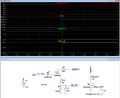
Below is the LTspice sim of a simple igniter continuity test circuit that implements my suggestion:

When the Pad x MOSFET is turned on (red trace) the LED current becomes ≈15mA (blue trace) for a nominal 12V in, and the Ctk_Ok digital monitor signal goes to 4.4V (yellow trace).

1730269268049.png
 

MisterBill2

Joined Jan 23, 2018
27,759
Certainly a modern wireless control system will be impressive! I hope it never gets hacked or triggered by a burst of electrical noise.
The safety benefit of the classic firing system was that it required a series of deliberate actions to launch. That is a useful safety feature.
I have designed the launch systems for a few crash sleds at one job. avoiding an accidental triggering was vital. So in addition to the computer control was ALWAYS a manual switch that had to be operated along with the software trigger function. So no computer issue can possibly trigger a launch without a deliberate operator action. Definitely old technology!!
 

Thread Starter

phillipsoasis

Joined Aug 22, 2022
170
Below is the LTspice sim of a simple igniter continuity test circuit that implements my suggestion:

When the Pad x MOSFET is turned on (red trace) the LED current becomes ≈15mA (blue trace) for a nominal 12V in, and the Ctk_Ok digital monitor signal goes to 4.4V (yellow trace).

View attachment 334691
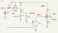
I adapted your circuit to my project and can't replicate your simulation values. The LED does not turn on.
My changes:
1. The gate of the MOSFET is driven from a voltage source of 0 - 3.3V, depending on how much current I want to have in the igniter. To check continuity, I would use a short pulse of a few 100 mV to the gate to pull enough current to turn on the LED and drive the Continuity signal high, but not the igniter.
2. The MOSFET source is connected through a 0.1R sense resistor to ground for feedback to control the gate voltage. No need for the feedback in this model.
3. Startech igniters have a nominal resistance of 1R, but 10R is OK.
4. Continuity (your Ckt_OK) is limited to 0-3.3V for a GPIO pin to read, so I changed your D3 to a 3.0V zener diode.
5. I changed your V1 to 15V, the nominal voltage of my battery pack
4. I left your resistor values the same.
 

Attachments

crutschow

Joined Mar 14, 2008
38,584
I adapted your circuit to my project and can't replicate your simulation values. The LED does not turn on.
You circuit is essentially identical to mine so why does yours work and not mine?
The gate of the MOSFET is driven from a voltage source of 0 - 3.3V, depending on how much current I want to have in the igniter. To check continuity, I would use a short pulse of a few 100 mV to the gate to pull enough current to turn on the LED and drive the Continuity signal high, but not the igniter.
The current is limited to about 20mA by R101 in your schematic, which should not be enough to ignite the igniter even with the MOSFET fully on.
 

Thread Starter

phillipsoasis

Joined Aug 22, 2022
170
You circuit is essentially identical to mine so why does yours work and not mine?
The current is limited to about 20mA by R101 in your schematic, which should not be enough to ignite the igniter even with the MOSFET fully on.
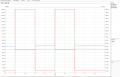
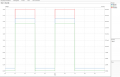
That is why I am confused! This is what I am seeing.
I have attached copies of my spice models. I checked the pins and they are correct from the schematic to the model.
 

Attachments

Last edited:

eetech00

Joined Jun 8, 2013
4,709
Suggestions,

Suggestions to the referred to the circuit in post #9-
1. Move the addressable selector so it is between the DAC output and the VTC circuit. This keeps it out of the VTC feedback path.
2. Use an opamp across the sense resistor to monitor "continuity" current. This would provide a complete check including the mosfet. The threshold current can be set to indicate "go" or "no go". Use this output to key the wireless "continuity signal", and drive a mosfet to light an indicator (LED or Incandescent). This would be repeated for each igniter. I think cost would be acceptable?
3. Regarding the mosfet "offset" components, why needed? Couldn't this be handled by the DAC control voltage?
 

Thread Starter

phillipsoasis

Joined Aug 22, 2022
170
Suggestions,

Suggestions to the referred to the circuit in post #9-
1. Move the addressable selector so it is between the DAC output and the VTC circuit. This keeps it out of the VTC feedback path.
2. Use an opamp across the sense resistor to monitor "continuity" current. This would provide a complete check including the mosfet. The threshold current can be set to indicate "go" or "no go". Use this output to key the wireless "continuity signal", and drive a mosfet to light an indicator (LED or Incandescent). This would be repeated for each igniter. I think cost would be acceptable?
3. Regarding the mosfet "offset" components, why needed? Couldn't this be handled by the DAC control voltage?
Regarding #1 and #2, let me look into those ideas. Thanks!
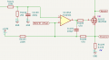
Regarding #3. You are correct in theory, but in practice (i.e. when I built the prototypes), the MOSFET never turned off. I think it was do to offset currents in the op-amp. I wanted the MOSFET hard off when attaching the igniter to the wires, so I added the offset to the op amp to insure it was hard off when I told it to be hard off. The current was small and should not have been enough to cook off the igniter, and I have a manual switch that kills the power to the igniter, but I still wanted the MOSFET OFF when I told it to be off! My fingers were the ones at risk! ;) Small model rocket engines burn at 3,000 F.
 

eetech00

Joined Jun 8, 2013
4,709
Regarding #1 and #2, let me look into those ideas. Thanks!
Regarding #3. You are correct in theory, but in practice (i.e. when I built the prototypes), the MOSFET never turned off. I think it was do to offset currents in the op-amp. I wanted the MOSFET hard off when attaching the igniter to the wires, so I added the offset to the op amp to insure it was hard off when I told it to be hard off. The current was small and should not have been enough to cook off the igniter, and I have a manual switch that kills the power to the igniter, but I still wanted the MOSFET OFF when I told it to be off! My fingers were the ones at risk! ;) Small model rocket engines burn at 3,000 F.
3 - undestood

The opamp you are using has a shutdown pin. Perhaps this could be used to shutdown and remove voltage to the gate. Additionally, perhaps the continuity threshold current could be set to a value that would indicate “unsafe” condition.
 

Thread Starter

phillipsoasis

Joined Aug 22, 2022
170
Regarding #1 and #2, let me look into those ideas. Thanks!
Regarding #3. You are correct in theory, but in practice (i.e. when I built the prototypes), the MOSFET never turned off. I think it was do to offset currents in the op-amp. I wanted the MOSFET hard off when attaching the igniter to the wires, so I added the offset to the op amp to insure it was hard off when I told it to be hard off. The current was small and should not have been enough to cook off the igniter, and I have a manual switch that kills the power to the igniter, but I still wanted the MOSFET OFF when I told it to be off! My fingers were the ones at risk! ;) Small model rocket engines burn at 3,000 F.
Regarding #1. If I put the address selector after the DAC, won't I have to duplicate all of this circuitry for each igniter? I am trying to reduce both cost and pcb real estate as I stamp out 64 igniter circuits. Replicating just the MOSFET for each igniter appears to be the least cost in terms of component count as well as dollars.
 

Attachments

Thread Starter

phillipsoasis

Joined Aug 22, 2022
170
3 - undestood

The opamp you are using has a shutdown pin. Perhaps this could be used to shutdown and remove voltage to the gate. Additionally, perhaps the continuity threshold current could be set to a value that would indicate “unsafe” condition.
I had not noticed that feature. It turns out the parts I ordered for my prototypes are the ones without the Shutdown pin. I will have to order some with the shutdown pin and test it! Thanks!
 
Top