Looking for ways to expand a design from single use to multi-use

eetech00

Joined Jun 8, 2013
4,723
Regarding #1. If I put the address selector after the DAC, won't I have to duplicate all of this circuitry for each igniter? I am trying to reduce both cost and pcb real estate as I stamp out 64 igniter circuits. Replicating just the MOSFET for each igniter appears to be the least cost in terms of component count as well as dollars.
Yes, my suggestions would need to be repeated for each igniter, but I think the benefits would outweigh the costs but its up to you. The result should be better monitoring and control of the igniter current. I think its not a good idea to have the selector in the feedback path of the voltage to current converter. The circuits in previous posts don't really provide a complete continuity check (including the mosfet). The opamp could be a dual RR type, but may also need a comparator with PU/PD output to drive the mosfet.
 

MisterBill2

Joined Jan 23, 2018
27,963
Why not use one complete circuit and an 8 by ten switching arrangement to select the next device to be triggered. An 8 position two pole rotary switch to select the row, and then an eight level ten position selector to choose the column. The switches would last because they will never break or make with any current present.
Also, specifying the voltage rather than the current would make sense if the connections were all low resistance connections. AND, given that the resistance of each igniter type, an appropriate voltage can be determined.
 

Thread Starter

phillipsoasis

Joined Aug 22, 2022
170
Why not use one complete circuit and an 8 by ten switching arrangement to select the next device to be triggered. An 8 position two pole rotary switch to select the row, and then an eight level ten position selector to choose the column. The switches would last because they will never break or make with any current present.
Also, specifying the voltage rather than the current would make sense if the connections were all low resistance connections. AND, given that the resistance of each igniter type, an appropriate voltage can be determined.
I am not sure how I move the rotary switch when I am standing 20 feet away. We are talking about a wireless launcher, where the box is at the launch stand and the user is 20 feet away and there are no wires in between them.
 

crutschow

Joined Mar 14, 2008
38,668
I think that perhaps using a high-side current-limit with a switched low-side MOSFET for each igniter, such as sghioto proposed in Post #16 might be the best way to go (along with the continuity test circuit I proposed of course).
You could use a low-side voltage controlled, high-side constant current circuit, if you want the current to be variable.
 

crutschow

Joined Mar 14, 2008
38,668
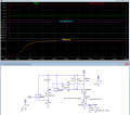
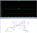
Below is the LTspice sim of a high-side constant-current circuit controlled by the low-side DAC voltage:

When the Pad_x_Enable signal goes high, turning on M3 (top red trace), the igniter current goes to 5A (bottom traces) (shown for an Igniter resistance of 1Ω and 3Ω (middle traces)).

So for that circuit you only have to mux the gate voltage to M3, with all the igniters connected to the constant-current output (Node 4).

1730395982566.png
 

MisterBill2

Joined Jan 23, 2018
27,963
OK, no rotary switches then. So a panel of DPST relays selected by a 5-bit binary code will allow remote selection while using just one universal driver.
 

crutschow

Joined Mar 14, 2008
38,668
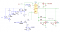
Is this correct?
Looks basically ok, but it would seem that the top self-test circuit from relay pin 1 is redundant, as the Q2 LED circuit already checks continuity.
Removing that would allow the elimination of all the isolation diodes to each igniter along with the use of a SPDT relay, as only one Pad x MOSFET is on at a time.

Also he is using 3V logic so D3 should be a 3V Zener.
He showed a 1730410392033.png in post #32.

You show two different values for the Vin voltage.
 

sghioto

Joined Dec 31, 2017
8,737
Looks basically ok, but it would seem that the top self-test circuit from relay pin 1 is redundant, as the Q2 LED circuit already checks continuity.
Removing that would allow the elimination of all the isolation diodes to each igniter along with the use of a SPDT relay, as only one Pad x MOSFET is on at a time.
Do you mean to eliminate the Test Lamp and just use D2 as the visual indicator?
 

sghioto

Joined Dec 31, 2017
8,737
My view was that if the mosfet can power the lamp then it's good to go.
But I like your suggestion using D2 as the indicator as it does eliminate 128 diodes simplifying the circuit.
1730417007522.png
 
Last edited:

Thread Starter

phillipsoasis

Joined Aug 22, 2022
170
Yes, unless there is a good reason to have both.
The lamp only tests part of the circuit, while D2 checks the complete circuit.
This looks awesome! Thank you so much for your input!

I may be looking at circuit #54 incorrectly, but it seems to me that Q1102 has to be active to turn on the test lamp, so it does test the ignition circuit end to end. It does not test the continuity of the actual igniter, the other circuit does that.

The test lamp and LED serve slightly different purposes. The test lamp I can see from the launch table 20 feet from the launch stand, which is where this box sits (even under the worst lighting conditions). So, with a touch of a button on my phone the lamp will light (e.g. an automotive lamp) so I know the the ignition circuitry is working (not including the igniter).

The LED, which may or may not be visible from 20 feet away, is useful at the launch stand when I connected a new rocket's igniter or diagnosing a misfire when the rocket did not launch. I have a manual switch to kill all power to the ignition circuit for connecting the igniter. I can close the manual switch and step a few feet away from the launch stand, and then test if the continuity light glows. Same with a misfire - SOP is to wait a few minutes, then approach the rocket for a 360 degree examination, and then approach it. At that time the LED will be important to see of there is still continuity in that circuit.

I also have an indicator on the phone that tests the Ckt_OK signal so I can tell, for example, if a gust of wind knocked a clip off the igniter wire. The phone indicator is great for when I am not at the launch stand, the LED is great for when I am at the launch stand. I don't want to be looking at a phone and pushing buttons when approaching a misfire. I want all my focus to be on the rocket, as I have had misfires launch as I approach the launch stand.

As far as the diodes are concerned, let's call the vertical diode D1 (attached to the relay) and the horizontal diode (attached to the igniter) D2. I see how D2 prevents any current flow through the igniter when the test lamp is activated, which is great. I am not seeing the purpose of D1. When current flows through the igniter it has only one path and that is through the Pad1 Q1102. It can't go back through relay pin 1, as that pin is open, and it can't go through Pad2 Q1102 as that MOSFET is off. What am I missing?

Finally, one more question. Something I think about a lot when I am working on this project. What are the worst case scenarios in this design? Under what (failure) conditions could a second rocket launch when launching a rocket? Under what (failure) conditions could a rocket ignite when someone is attaching the igniter leads to an igniter? What are the catastrophic failure conditions for this circuit? How would I safe guard against these failures? In other words, thinking back to Apollo 13, under what conditions could stirring the liquid oxygen in the tanks cause them to explode, and how to prevent that?
 
Top