Okay, we're making good progress.
Those voltages now look near normal and you should be getting a PWM output when you adjust the pot (the voltage at node 5 , MOSFET output, should increase as you increase the pot output voltage).
Okay, we're making good progress.
Those voltages now look near normal and you should be getting a PWM output when you adjust the pot (the voltage at node 5 , MOSFET output, should increase as you increase the pot output voltage).
With R5 turned down, I plugged in the power, and slowly increased to half. There
is a short 1-2 second ramp up. I can flip the knob on R5 back and forth, the motor
revs up and down acordingly, I can load it, and no problems. However, when just
now I set it to about half speed, unplugged the motor power suppy only, waited
30 seconds, and then plugged it back in, I can hear the motor kick over, and then BAM!,
full speed, as the mosfet shorts.
Can you look at the PWM output with your meter and see if if there's about a second delay before the voltage starts to rise after the power is applied?
Can you look at the PWM output with your meter and see if if there's about a second delay before the voltage starts to rise after the power is applied?
Okay, I rewired it so that it's using classroom voltages. The 12 power supply
for the device also bridges over to the mosfet (2n7000) and I replaced the motor load
with a small automotive 0.25w bulb. When I quickly flick the pwm-potentiometer* to full, there is about a
3 second rise before full brightness. (This is the perfect bulb for a visual indication, as it will start glowing from 1.5v all the way to 35v.)
Then, I rotate the pwm pot to full, and turn off the 12v power supply. Then I switched on the 12v supply, and the bulb
rose from a weak intensity to full, taking about 3 seconds. I get a corresponding rise on my auxiliary meter, going from <1v to about 12v, in the same 3 seconds.
After trying this several times, I am satisfied that the device is working.
What is not working is switching the high voltage side for the mosfet on and off, while the 12v supply is still on.
I need to discover how I can switch both the 12v & HV simultaneously, and still retain the slower rise time of the pwm signal (I might already be there!). I also need to figure out a light-weight 12v supply, as I don't need anything close to the small 1A unit I a presently using.
I intend to be able to mount this close to the motor. Some advice has suggested that PWM at distance is hard on motors, with increased RFI. Anyway, this circuit could be very useful and adaptable for many different voltages and power. I hope so.
*In previous posts, I've been calling this "R5", a holdover from the old schematic. Sorry for any confusion.
EDIT: multiple edits for clarity. Time for bed.
Hi Hamlet, I did a lot of work with PWM switching 180V DC pumps. I found Mosfets to be pretty vulnerable despite high voltage and current ratings, snubbers, EMF diodes and good heatsinking. I switched to a single IGBT device (IXGH31N60D) with an IGBT driver (ACPL-P03/W302), both avail on Element14, and all of the problems went away. A lot of it is to do with how long the FET spends in the transition between Off and On. If the transition is slow (sawtooth-like) there is a lot of dissipation going on in that region. With the fast PWM of 15KHz there are lots of transitions-per-second going on and it hammers the devices. My application was solar powered water pumps under software control - direct from panels to motor, no batteries. Worked a treat.
Sure Hamlet, In short the project brief was: Pump water on a farm from a low dam into a header tank on top of a rise, maybe 60 metres higher. Solar panels in series driving a dc motor driving a PC (Progressive Cavity) pump. When the sun shines, it pumps. When the sun doesn't shine, it stops. Technical challenge: To ensure that the motor doesn't cook when there is a bit of sun, but not enough to run the pump.
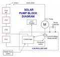
So I used an Atmel AVR micro and an assembly language program I wrote, which would 'wake up' when there was daylight. It would try to start the pump 3 times at 30 second intervals. If unsuccessful it would wait 10 minutes and try again. (There was a current sensor on the pump to tell the program if the start attempt was successful or not) The pump would have ten selectable PWM settings via a tiny 10-position binary encoder switch, so flow rates could be controlled. The micro drove the IGBT driver, which drove a single IGBT, to drive the pump. I had 4 x 24V panels wired in series as the only supply. No batteries or external power.
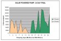
I set up a trial to recirculate water from a small cattle trough, to the top of a 16 metre radio tower. This dropped to a holding tank via a flow sensor & data logger, which then gravity fed back to the original trough. This loop allowed me to collect a lot of hard data on flow rates over many months. 4 panels in a Melbourne (Australia) winter moved 4100 litres per day. By adding a 5th panel it increased to 8600 litres per day (on average) In Summer, with longer daylight hours and more sun these two figures approximately doubled.
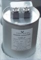
Useful tip: The PC style of pump are great because they pump to a high head of water, but they tend to be 'sticky' in that it took a burst of energy to crack the first movement, therafter they spun freely. Sometimes in cloudy weather, there was not enough energy to trip pump movement, but if I gave the drive pulley a kick with my foot it would then pump quite nicely. The solution was to put a bloody great electrocap and diode across the solar panel, so that with each start attempt the cap would have slowly charged enough to give a 2-second 'kick' to the motor start events. This made a big improvement to pumping rates at dawn/dusk and in and out of cloud cover.
So, that's something for you to think about. Cheers.
Last comment. The system also worked fine on smaller pumps. One 24V panel with a 24V pump. Flow rates were much smaller of course, but it was a cheaper system.
What is not working is switching the high voltage side for the mosfet on and off, while the 12v supply is still on.
I need to discover how I can switch both the 12v & HV simultaneously, and still retain the slower rise time of the pwm signal
So you would appear to need a lockout of the 12V if the HV is not on.
This could be a relay or MOSFET to control the 12V power, that is switched by the HV, so that the 12V doesn't come on until the HV is up.
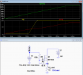
A circuit for that using an N-MOSFET is shown here.
It starts switching the 12V on when the 115V reaches about 40V.
Essentially there is a zenner and transistor combination on the 24V rail into the controller logic which gives a sharp 0V output if the solar panel drops below say 15V. This stops the micro going nuts during dawn/dusk brownouts. Once the micro is up and running, it measures the HV and decides whether or not there is enough juice to warrant a start event attempt. The micro also talks to a 2-line LCD display giving status readings and logs an hourmeter of run time in NV ram.
The project works fine, but I didn't commercialise it. I probably should one day.
Sure Hamlet, In short the project brief was: Pump water on a farm from a low dam into a header tank on top of a rise, maybe 60 metres higher. Solar panels in series driving a dc motor driving a PC (Progressive Cavity) pump. When the sun shines, it pumps.
Bravo. Infrastructure needs rugged solutions. Moving water is non-trivial, facilitating it is a noble task.
I like those positive cavity pumps. Handles dissolved solids/mineral water well. Often used for desal.
A good PWM design allow the use and reuse of a large variety of motors for the same task. Sorting out
this problem has applications for laths, mills, automotive, etc.
So you would appear to need a lockout of the 12V if the HV is not on.
This could be a relay or MOSFET to control the 12V power, that is switched by the HV, so that the 12V doesn't come on until the HV is up.
A circuit for that using an N-MOSFET is shown here.
It starts switching the 12V on when the 115V reaches about 40V.
I will implement this soon. Not sure if it will be today, as I have to meet with the local bureaucrats, who knows how long that'll take...
I noted that when using an independent supply thru the mosfet switch, I get a spike upon turn-off of the device. Not sure if that's important,
as I only discovered it when a bulb was connected under test conditions.
Turn on: HV on first, then pwm device second
Turn off: switch pwm device off, then HV
(HV first on, last off.)
Nice circuit Hamlet.
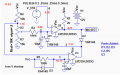
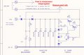
Here is the one I used, made from transistors and zenners It supplies power to the 5V switchmode regulator only when the 24V (unloaded) panel exceeded 30V, and removed power only when the 24V (loaded) panel fell below 21V. This ensures that the micro always had a viable supply in the range where it had to make decisions about pumping or not. I also put a bunch of electro's across the panel so it wouldn't drop out the micro everytime a bird flew over the panel area.

 Facebook
 Google
 GitHub
 Linkedin