Let me add, in case this makes a big difference (and it might) that
the 1/3 HP, 115v DC, 3A motor that I am using is of the shunt-wound type.
The stator and the rotor are connected in parallel, and in turn both are
receiving the PWM current.
I have been worried that there is no Under Voltage Lockout on the 12 Volt supply, but until in post # 20, there was nothing to suggest that it may be a problem.
What worries me is that when the 12 volt supply is turned on, there will be a short period where R8 pulls the bases of Q1 and Q2 up. If this "impulse" reaches a voltage where Q3 begins to draw current, so it is potentially quite a lot of power to be "burned" by the MOS transistor.
I switch everything off (yank the plug out of the wall),
pause for 30 seconds, then plug back in, expecting a short delay, then a mild ramp up to speed...
but instead, the mosfet blows, the motor runs away at full speed.
Do you have a 'scope to look at the signals?
I suspect that the comparator plus voltage may be going high before the sawtooth from the 555 is there and that would cause the comparator U2a to come up high for a fraction of a second, zapping the MOSFET.
You could clamp both the plus input and the comparator output for a second or so during startup to absolutely insure that the MOSFET is off (using 1 transistor and two diodes or two transistors) during the time the 555 takes to generate a normal sawtooth.
When the transistor(s) releases, then the PWM ramp-up would start.
(We want to save those last three cartridges.)
Do you have a 'scope to look at the signals?
I suspect that the comparator plus voltage may be going high before the sawtooth from the 555 is there and that would cause the comparator U2a to come up high for a fraction of a second, zapping the MOSFET.
You could clamp both the plus input and the comparator output for a second or so during startup to absolutely insure that the MOSFET is off (using 1 transistor and two diodes or two transistors) during the time the 555 takes to generate a normal sawtooth.
When the transistor(s) releases, then the PWM ramp-up would start.
(We want to save those last three cartridges.)
No, I don't have a scope, yet.
In the meantime, I can try to clamp the + on the comparator (pin 5) and the output on the comparitor (pin 7), yes?
I have lots of diodes and transistors, what does a "clamp" look like?
I have three new IRF640 mosfets, and a handful of pulls that are rated for 200v+.
I'm going to order more IRF640 today, and perhaps IRFP250 or 260.
After noticing you have a spare LM393, I used that to generate the turn-on clamp delay circuit below:
The U3 comparator output is low until its (+) input exceeds the (-) input voltage as determined by the R5C2 delay.
This keeps both the pot output and the MOSFET signal low through diodes D1 and D2.
Diode D3 rapidly discharges C2 when the power is removed s0 it's instantly ready for the next power-on cycle.
The diodes can be just about any type.
The startup delay for the R5C2 values shown is about 1 second, then the voltage at node 3 (U1 +in) starts to charge, and after about another second, the PWM signals to the MOSFET start to ramp.
If that doesn't solve your problem, I'm having a drink.
I isolated the 12v power from the motor power. Now the 12v supply is always on, with only the motor power supply switching in and out.
This works okay with a slow roll on of R5.
I was going to do the full-on test, with R5 rolled up to 3/4 or so, but now I am hesitating because I don't know if that will prove anything...
Okay, no drinking yet! I added the componets as shown. I plugged in my 12v supply. I plugged in my HV supply for the motor.
I twisted R5 up and... nothing. I checked my work, looks good, diodes right direction, etc.
After days and days of rain, I am going to go outside and play. I will be back later. Thank you for all the help so far...
You'll need to use a meter to see which voltage is incorrect.
If you post the voltage at all the nodes, I can help with that.
Just mark each node on the schematic with a number to make it easy to reference its respective voltage.
Okay, I've made the changes. I've got the delay we're looking for, but, I'm still blowing mosfets.
With the first mosfet, I played with R5, testing the delay, with things going smoothly. Then I loaded
it until mosfet failure, which was 8A or so. Okay, good to know. I replace the mosfet.
With R5 turned low, I apply 120v ac to my two power supplys, one for the motor, and the 12v supply
for the device. I roll the pot on to the halfway mark, wait a few moments, and it spins up the motor. Fine.
Then, while leaving the R5 at the new setting, I switch everything off (yank the plug out of the wall),
pause for 30 seconds, then plug back in, expecting a short delay, then a mild ramp up to speed...
but instead, the mosfet blows, the motor runs away at full speed.
Mind, in this test, the motor was not loaded. At the half setting on R5 on an unloaded motor, it only
draws one amp, running about 3/4 speed.
Okay, here's where I'm at... I've rebuilt twice, consulted datasheets, replace most parts, substituted 22uF & 4.7uF for the two caps,
used film caps for in place of ceramic decoupling caps, etc.
I went back to the original circuit, that works fine.
Then I carefully built stage two, with the 100k resistor and 10uF cap. This stage works, sometimes. At other times,
I have noticed that it just scintillates, which is to say, I can hear a whine from the motor, but no start. If I crank
up R5 further, there's a risk that it will start with a bang, blowing the mosfet.
Stage three: it just sits there, no movement, no noise, but no bang either.
I took all those parts off, and it behaves as before.
I could try something else, or I could source some really large mosfets? IRFB4229 maybe?
On my breakout board, I had a short between pin 3 and ground. I knew this and promptly forgot it, as
I was planning on grounding the unused half of the comparitor. After I corrected this, operation improved, but
I still can't set R5 at some advanced position, and then energize without blowing the fet. At the lower settings
on R5 it is okay, but the motor jumps/starts at a bit higher RPM, and then immediately drops down.
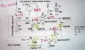
Here are the voltages. Three of the nodes were already marked, and I added 4, 5, 6, & Vcc. These were measured with R5 at the lowest setting, if that helps.
Okay, right off I see that node 1 at U3's (+) input should be 12V, so there's a problem there.
With that sitting at .199V the outputs stay clamped.
The output has to go higher than the voltage at U3"s (-) input (node 4).
Is the polarity of C2 correct?
How about C1?
The node 4 voltage is also incorrect. It should be near 8V with the three 10k ohms resistors in series from the 12V.
It would appear that one or more of those resistors are an incorrect value.
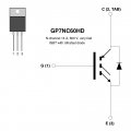
Can't add much. But I did scrap an old garage door opener. The motor is rated at 140 VDC and the FET that drives it is a GP7NC60HD. (pictured below) The IGBT is an insulated gate bipolar transistor controlled by a MOSFET. A hybrid of sorts. I JUST learned this stuff. I'm old school electronics. New to the stuff available today. Haven't kept up with the changes and now seriously lag behind in my knowledge of devices and what's available out there. Only this past Tuesday did I learn what an IGBT is.
Okay, right off I see that node 1 at U3's (+) input should be 12V, so there's a problem there.
With that sitting at .199V the outputs stay clamped.
The output has to go higher than the voltage at U3"s (-) input (node 4).
Is the polarity of C2 correct?
How about C1?
The node 4 voltage is also incorrect. It should be near 8V with the three 10k ohms resistors in series from the 12V.
It would appear that one or more of those resistors are an incorrect value.
Node #1 polarity of C1 & C2 are correct. This is my 3rd set of caps there, all different mfg.
Node #4 I replaced the 10k resistors with something more accurate, and the pot R5 is 10k.

 Facebook
 Google
 GitHub
 Linkedin