Looking for a good high voltage MOSFET for a PWM design

Thread Starter

Hamlet

Joined Jun 10, 2015
560
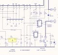
Essentially there is a zenner and transistor combination on the 24V rail into the controller logic which gives a sharp 0V output if the solar panel drops below say 15V. This stops the micro going nuts during dawn/dusk brownouts. Once the micro is up and running, it measures the HV and decides whether or not there is enough juice to warrant a start event attempt. The micro also talks to a 2-line LCD display giving status readings and logs an hourmeter of run time in NV ram.
The project works fine, but I didn't commercialise it. I probably should one day.
I'm was anticipating C+ and micro for this project, but if a linear solution is more direct, then I'd prefer that.
Nice solution for powering the micro. I have a couple of projects threads here using a device that mimics
whatever it is that a solar LCB does. Those devices are less than robust, and long lead
times, with very little documentation, perhaps because only two companies have commercialized it.
You might do that, and give the competition some schooling.
 

Thread Starter

Hamlet

Joined Jun 10, 2015
560
So you would appear to need a lockout of the 12V if the HV is not on.
This could be a relay or MOSFET to control the 12V power, that is switched by the HV, so that the 12V doesn't come on until the HV is up.

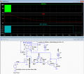
A circuit for that using an N-MOSFET is shown here.
It starts switching the 12V on when the 115V reaches about 40V.

View attachment 120704
Ah, a mosfet has some inherent capacitance,
the gate slowly charges up. I think I'm beginning to understand.
 

crutschow

Joined Mar 14, 2008
38,844
Ah, a mosfet has some inherent capacitance,
the gate slowly charges up. I think I'm beginning to understand.
The gate does have capacitance, but that's not why the threshold is about 40V.
That's actually the Vgs(th) of the MOSFET, from the resistive divider action of R2 and R3.
Remember that the N-MOSFET is acting as a source-follower here. It's the gate-source voltage that determines when it turns on.
Thus, when the applied voltage reaches about 40V, the gate-source voltage from the voltage divider reaches the MOSFET threshold voltage (4V for the particular MOSFET in the simulation), and it starts to turn on.
Then at some Vgs above this threshold, the MOSFET becomes fully turned on, with its minimum on-resistance.

The graph below plots the gate-source voltage [V(G,S)] as the motor voltage goes to 115V and back to zero, to show this:

upload_2017-2-17_11-40-46.png
 
Last edited:

ronsoy2

Joined Sep 25, 2013
71
The plot above must be in error? This indicates the FET is in linear operation for many milliseconds! See the safe operating area for the transistor. ZAP! The FET MUST be switched in MICROSECONDS from off to on, and on to off. The FETs specified in the post are NOT rated for operation in their linear region at all! This is why the switch mode driver has to have good current capability to drive the large capacitance of the gate quickly.
A point that has not been noticed here is that the motor was mentioned to be a shunt motor! The shunt motor has virtually zero impedance with no field current! The rated starting current is with FULL field voltage on the field winding. If the field is in parallel with the armature, and both are started at zero at the same time there will be a tremendous current pulled until the field magnetism builds up. This is possibly the reason the circuit is taking out the FETs, not the controller. The field current in a shunt motor must be applied well before armature current to keep the armature current from being limited by only the resistance of the armature winding. Changing to a permanent magnet motor is one solution, a series wound motor another. Or a relay circuit that will pull in from the field voltage to then apply the armature voltage after the field is energized.
 

crutschow

Joined Mar 14, 2008
38,844
The plot above must be in error? This indicates the FET is in linear operation for many milliseconds! See the safe operating area for the transistor. ZAP! The FET MUST be switched in MICROSECONDS from off to on, and on to off.
Easy now -- ;)
There's no error and no ZAP.
That MOSFET only switches the small 12V control circuit current (<<1A) so there's no problem if it operates for a short time in the linear region.
It will stay well within its safe operating limits.
The time in the linear region actually depends upon how long the 115V takes to ramp up.
Even if that's seconds, it wouldn't be a problem.
 
Last edited:

Thread Starter

Hamlet

Joined Jun 10, 2015
560
Just an update: the lockout circuit works great!

I did blow another mosfet, this time under extreme load on
startup, but this 'fet was an underspec pull I sourced from my junkbox.
I ordered better mosfets, should be here next week or so.
I might also try an IBGT, just for the heck of it. Thanks to Fixup
for sharing that insight. My only concern is perhaps to develop
some kind of safety that shuts down the motor if the mosfet
fails in the shorted state. Voltage could then go as high as 170v or so.

Much appreciation to everyone who helped sort this out, share ideas,
and especially a big thumbs up to Crutscow, for sticking with me
on this problem 'till the end. Thank you friend. One day I hope to be half as smart.
 

Thread Starter

Hamlet

Joined Jun 10, 2015
560
Is that a problem?
Well, yes. The type of pump I'm working with has speed range of 1400 to 1725rpm.
50% faster is too much. If placed a remote location, I wouldn't hear it overspeeding
in the case of a mosfet failure.
 
Last edited:

Thread Starter

Hamlet

Joined Jun 10, 2015
560
How about just reducing the maximum motor voltage?
I don't have an easy way to do that. This is why I chose PWM. My max supply voltage is fixed,
either 170v DC for rectified/smoothed mains, or 140v DC for rectified/smoothed square-wave inverter.

I am envisioning a system that has one pump for supply to a reservoir, and one or more pumps for pressurizing.
The PWM circuit will be for pressure pumps.

Perhaps a voltage divider with a relay as a safety cut off. If the mosfet shorts closed, the coil gets enough voltage to open the relay
that supplies power to the motor...
 

crutschow

Joined Mar 14, 2008
38,844
You could look at the average (filtered) voltage across the MOSFET.
If it stays at zero for a significant length of time, indicating a shorted MOSFET, then you could use that to open the relay.

Below is the simulation of a circuit to do that.
The NO relay contact is closed when there is power and a PWM signal at the MOSFET drain.
The PWM source signal is filtered by R1C1 and goes low with a delay [V(1)] after the simulated PWM gate signal stops and goes high (simulating a shorted MOSFET).
This turns off transistors Q1 and Q2, opening the relay and power to the motor some 9 seconds later.

As long as the PWM signal average is at least 1.5V, the relay will stay pulled in.

C1 is connected to the +12V so that [V(1)] will go high and energize the relay when power is first applied.
(Note C1 polarity).

D1 clamps the V(1) voltage to ≈13V maximum (about 0.7v greater than the 12V supply).

upload_2017-2-19_12-39-40.png
 
Last edited:

Thread Starter

Hamlet

Joined Jun 10, 2015
560
Thanks!
I printed this off and am studying it. I'm sure I have the parts to implement this,
I just need to "see" how it fits in with the big picture. Everything is closed
tomorrow except the tiki bar, so chances are 50/50 I won't be distracted...
 

vrainom

Joined Sep 8, 2011
126
Hi, just for kicks, what kind of flywheel diode are you using, maybe it's not the right kind?

Also, you say you're using a shunt wound motor, in that case you should always excite the field with the full DC voltage in order to create the field magnetism, if you're also varying the field power the field won't create the proper magnetic repulsion and the armature current shoots up.

Hope this helps.
 

Thread Starter

Hamlet

Joined Jun 10, 2015
560
Hi, just for kicks, what kind of flywheel diode are you using, maybe it's not the right kind?

Also, you say you're using a shunt wound motor, in that case you should always excite the field with the full DC voltage in order to create the field magnetism, if you're also varying the field power the field won't create the proper magnetic repulsion and the armature current shoots up.

Hope this helps.
I am currently using an RF1501N, 20A, 300v. Was using a 1N5004. No difference that I can tell.

I realize that there is a lot of conventional wisdoms concerning shunt wound motors that I am not following.
My opinion is that the field power is the same as the arm. at any given instantaneous moment (pwm). Perhaps
the core isn't have time to saturate, i dunno.

Unfortunately, the armature & field is parallel connected behind a fibered insulator that is behind another plate in the motor.
I'd have to tear the whole thing down to lead out the arm & field separately. (Which I might do before I am through).

Just now I tried to use an old mosfet "pull" rated for 10A. I blew it, but not before getting a few readings on a linear
panel meter that I wired up specifically to catch the action. With no load on the motor, it draws 11A on start.

As for Crutschow's shutdown-circuit which kills the HV in the event of a blown mosfet, I was hesitant to try it because
I thought it might interfere with12v lockout circuit implemented previously. I only have one suitable mosfet left, I don't
want to loose it. I have more fets on the way, next week. Still, no guts, no glory, so perhaps I'll give it a shot. I can't play
outdoors with all this cold rain anyway...
 

crutschow

Joined Mar 14, 2008
38,844
As for Crutschow's shutdown-circuit which kills the HV in the event of a blown mosfet, I was hesitant to try it because
I thought it might interfere with12v lockout circuit implemented previously.
Unless the 150V turnon is very slow, the shutdown circuit should turn on much faster than the lockout circuit takes to operate, so there shouldn't be any interference between the two.
 

Fixup

Joined Feb 9, 2017
9
If you have to buy more motor driver parts, you may as well try an alternative to the MOSFET option. Something like one of these will do it: http://au.element14.com/ixys-semiconductor/ixgh20n120a3/igbt-1200v-20a-to-247/dp/1829738
The best way to drive them is with a dedicated device designed for the job. Check out:http://au.element14.com/broadcom-limited/acpl-p302-000e/optocoupler-smd-igbt-driver/dp/1640555

The data sheets for both devices are at these pages. I have also added a circuit fragment showing how this was connected. It should fix your switching issues. It sounds like things are a bit wet where you are. You have a good indoor project.
 

Attachments

vrainom

Joined Sep 8, 2011
126
I am currently using an RF1501N, 20A, 300v. Was using a 1N5004. No difference that I can tell.

I realize that there is a lot of conventional wisdoms concerning shunt wound motors that I am not following.
My opinion is that the field power is the same as the arm. at any given instantaneous moment (pwm). Perhaps
the core isn't have time to saturate, i dunno.
I wouldn't be surprised if the rf1501n diode ends up shorted because of the lowish reverse break down voltage.

What you got to have in mind with these type of motors is that the field winding has a lot more turns (hundreds or thousands) than the armature winding, so its inductance is a lot higher and it doesn't respond well to sudden changes in voltage. That might be why when you turn it on suddenly the mosfet gets fried. Also as far as I know the current going into the field shouldn't be varied beyond -20% of its nominal value. Let me tell you, once I connected a motor in parallel to a dc drive and I ended up frying the scrs.
 

Thread Starter

Hamlet

Joined Jun 10, 2015
560
I wouldn't be surprised if the rf1501n diode ends up shorted because of the lowish reverse break down voltage.

What you got to have in mind with these type of motors is that the field winding has a lot more turns
I switched out the diodes as a test. I forgot to check the datasheet, thanks.

I have two of these motors.
̶I̶ ̶d̶o̶n̶'̶t̶ ̶k̶n̶o̶w̶ ̶w̶h̶y̶ ̶a̶n̶y̶o̶n̶e̶ ̶w̶o̶u̶l̶d̶ ̶b̶u̶i̶l̶d̶ ̶a̶ ̶s̶h̶u̶n̶t̶ ̶w̶o̶u̶n̶d̶ ̶m̶o̶t̶o̶r̶ ̶a̶n̶d̶ ̶n̶o̶t̶ ̶b̶r̶e̶a̶k̶ ̶o̶u̶t̶ ̶t̶h̶e̶ ̶w̶i̶n̶d̶i̶n̶g̶s̶ ̶s̶o̶
̶t̶h̶a̶t̶ ̶y̶o̶u̶ ̶c̶o̶u̶l̶d̶ ̶a̶d̶j̶u̶s̶t̶ ̶t̶h̶e̶ ̶a̶r̶m̶.̶ ̶v̶o̶l̶t̶a̶g̶e̶ ̶f̶o̶r̶ ̶s̶p̶e̶e̶d̶ ̶c̶o̶n̶t̶r̶o̶l̶.̶ ̶T̶h̶a̶t̶'̶s̶ ̶w̶h̶a̶t̶ ̶t̶h̶e̶s̶e̶ ̶m̶o̶t̶o̶r̶s̶ ̶a̶r̶e̶ ̶m̶a̶d̶e̶ ̶f̶o̶r̶,̶ ̶a̶f̶t̶e̶r̶-̶a̶l̶l̶.̶
̶P̶e̶r̶h̶a̶p̶s̶ ̶i̶t̶ ̶w̶a̶s̶ ̶f̶o̶r̶ ̶a̶n̶ ̶a̶p̶p̶l̶i̶c̶a̶t̶i̶o̶n̶ ̶w̶h̶e̶r̶e̶ ̶t̶h̶e̶ ̶d̶c̶ ̶v̶o̶l̶t̶a̶g̶e̶s̶ ̶w̶e̶r̶e̶ ̶a̶l̶r̶e̶a̶d̶y̶ ̶a̶v̶a̶i̶l̶a̶b̶l̶e̶,̶ ̶a̶n̶d̶ ̶t̶h̶e̶ ̶s̶p̶e̶e̶d̶ ̶w̶a̶s̶ ̶f̶i̶x̶e̶d̶.̶ ̶:̶c̶o̶n̶f̶u̶s̶e̶d̶:̶

I just had a second look, and to my surprise and pleasure, the terminals are such that it is easier than I first thought
to isolate the windings. Turns out the field is wired from behind to a lead-thru terminal block, and the armature leads
come from the back and bolt to the front. This opens up additional possibilities.

Now to get on with it :rolleyes:
 

Thread Starter

Hamlet

Joined Jun 10, 2015
560
If you have to buy more motor driver parts, you may as well try an alternative to the MOSFET option. Something like one of these will do it:
Thanks for reminding me. I can always use something like that eventually, if not now.
 
Top