Just some general questions about remaking something from the past

Status
Not open for further replies.

Thread Starter

Berzerker

Joined Jul 29, 2018
623
AG said:
Post #420
MisterBill was referring to an earlier post when we talked about having the transformers rewound on the original design.
I am going to order (6) IC's AG for spares and future projects. Now the bridging sounds like a great idea.
And I meant to say I didn't know how many views this post had got till the 502 error the other day. Never paid the front page any attention.
I just leave my browser here cos I can't help anyone anyway. Just saying it amazed me.
 

shortbus

Joined Sep 30, 2009
10,049
I think the word layer is used to mean a lot of different things in different contexts.

There's only one copper layer on a single sided PCB, but DipTrace also refers to solder mask, silkscreen, etc. as layers:
I know that but, I was thinking that he thought he needed all of them on at one time. As a first board and learning type thing, I'd only be worried about the copper layer. May be wrong about this but it seems like he is going to have a bunch of these boards made at a board house and hope that the thing will work "right out of the box". Hasen't been like that in my experience.:(
 

shortbus

Joined Sep 30, 2009
10,049
Yes I have all that. The other 11 holes are to connect wires to so I can lay the TDA7396 down flat on the heat plate. If not I would have to bend the plate down to connect it to which cost more money. It's the way I'm designing it. Trying to get by with a flat plate I guess is what I'm saying. This is a separate PCB to connect to the main PCB.
Then if it is a separate PCB it doesn't get shown on the PCB you're working on now.

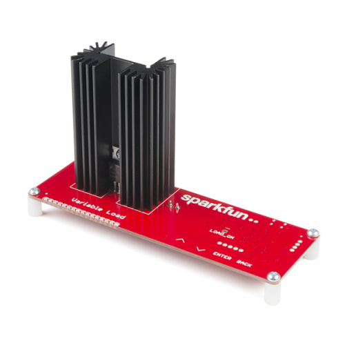
Here is a picture of the type of heat sink made for that type of IC and how it looks mounted to a board. It has a couple of pins sticking out of its bottom that go into holes in the board holes that other traces stay away from.
Here is a link to one place that sells the sink, https://www.sparkfun.com/products/9576 A real heat sink with fins will do more than a flat plate of the same size, especially one that is laying flat on the board.


Thread Starter

Berzerker

Joined Jul 29, 2018
623
shortbus said:
I know that but, I was thinking that he thought he needed all of them on at one time. As a first board and learning type thing, I'd only be worried about the copper layer. May be wrong about this but it seems like he is going to have a bunch of these boards made at a board house and hope that the thing will work "right out of the box". Hasen't been like that in my experience.:(
Please don't think I'm that crazy shortbus. I found a PCB manufacturer that will make 6 PCB's for $10.00 (within a reasonable size) I plan to build 2 or 3 to see if they work first. As I learned about mechanical design I also learned that you build one and test it, If there's a flaw you fix it. But one thing I can give AutoCad is you can test stress and a whole lot of other things before you buy or build anything. You can't just throw things together and cross your fingers and hope it works. I bought a radio as I said yesterday with 120W (30 per channel). Sometime today I will open it and test all the voltages on it and see what's really there. I will build an extra one and really put it to the test (?). In other words I want to see exactly what it will take to blow a TDA7396 up. I want to see if it can handle 30W going into it. From looking on the datasheet this is not mentioned. You know some idiot out there is going to hook it up to some outrageous Watts and I want to know what will happen. I was also hoping I might ask someone here to at least open my PCB's up in diptrace just to check them real quick and make sure there are no mistakes. Never hurts to ask.
 

ebeowulf17

Joined Aug 12, 2014
3,307
I was also hoping I might ask someone here to at least open my PCB's up in diptrace just to check them real quick and make sure there are no mistakes. Never hurts to ask.
No guarantees on timing, but if you share your DipTrace files, I should be able to check them out within a day or two...

but just in terms of the DipTrace files making sense as far as layer selections, DRC errors, etc. I'm not analyzing the circuit design itself - I have very limited audio circuit experience, and I've had a hard time keeping up with the numerous plans thrown out in this thread.

If you're content with your schematic, I can help make sure the PCB design reflects that schematic. If you want confirmation on the schematic, that'll have to come from someone else.
 

Thread Starter

Berzerker

Joined Jul 29, 2018
623
Thanks ebeowulf. That's all someone can ask for.
Got another stupid question, I was going to hook up the radio I got to a 110VAC to 12VDC adaptor but the voltage coming out is 16VDC.
Is this to much to put on a radio? don't want to blow it up right of the bat even if it wasn't but $17.00. Or should I get a battery and charge it and go from there ?. I think I still got one of my great nephews batteries from a those little electric cars.
Got the battery and the charger and the charger that goes with the electric car is only putting out 14VDC
 
Last edited:

Thread Starter

Berzerker

Joined Jul 29, 2018
623
OK I think I have my components right now (?). Been looking at the datasheet and I don't think I will need all the resistors (?)
I'm not going to use and the CD-DIA which I think goes to a diagnostic device or indicator of some sort and if I use the test circuitry diagram I only need two different resistors.
List: (6) TDA7396
https://www.digikey.com/product-det...MIt7KT5rGX3QIVVJ7ACh39yQJyEAAYAiAAEgJ3c_D_BwE
Capacitors:
(6 to 8) 0.1uf
https://www.digikey.com/product-detail/en/vishay-bc-components/K104K15X7RF5TL2/BC1084CT-ND/286706
(6 to 8) 10uf
https://www.digikey.com/product-detail/en/nichicon/UVR1H100MDD1TD/493-5915-1-ND/3438479
1000uf
https://www.digikey.com/product-detail/en/nichicon/UVR1H102MHD/493-1111-ND/588852
(6 to 8) 0.22uf
https://www.digikey.com/product-detail/en/epcos-tdk/B32529C0224J189/495-2522-1-ND/2649143
Resistors:
(6 to 8) 10 kohm
https://www.digikey.com/product-det...ronics-inc/CF18JT10K0/CF18JT10K0CT-ND/2022766
(6 to 8) 51 kohm
https://www.digikey.com/product-det...ronics-inc/CF18JT51K0/CF18JT51K0CT-ND/2022783
 

Thread Starter

Berzerker

Joined Jul 29, 2018
623
Been looking at heatsinks and found one I liked. Where are the footprints located in diptrace. Or can I just make a pattern by itself and insert it (?). Or do I just make one up while I'm in the PCB layout (?).
 

bertz

Joined Nov 11, 2013
327
Been looking at heatsinks and found one I liked. Where are the footprints located in diptrace. Or can I just make a pattern by itself and insert it (?). Or do I just make one up while I'm in the PCB layout (?).
Selecting a heat sink is not about finding one you like or if it fits your case. Its a bit more complicated than that. It would seem you have more reading and studying to do. You can try here for a start:

https://www.designworldonline.com/how-to-select-a-suitable-heat-sink/
 

shortbus

Joined Sep 30, 2009
10,049
Might need one a little shorter but I'm looking into that too. maybe 1.25" tall or so. I'm trying to make as low a profile as I can.

Been looking at heatsinks and found one I liked. Where are the footprints located in diptrace. Or can I just make a pattern by itself and insert it (?). Or do I just make one up while I'm in the PCB layout (?).
Like Bertz said you don't do things like your doing, especially not if you plan to market these. There will be something in the chip data sheet that tells you how much heat it puts out. There will be a similar thing in the data sheet for a heat sink. They have to be close in the amount of watts they can handle. You don't do this kind of stuff by, "how it looks to you". If more room is needed to fit in the heat sink you need to adapt the case size, or risk overheating the circuit.

I found a PCB manufacturer that will make 6 PCB's for $10.00 (within a reasonable size) I plan to build 2 or 3 to see if they work first.
Why not do it on Vero board first? Many of the guitar pedal builds never even get into a PCB because they do well without even needing one using point to point wiring. Then after you get a functioning design you draw a real schematic and make a board. This is how most people do it, or any experimental circuit.
 

ebeowulf17

Joined Aug 12, 2014
3,307
Been looking at heatsinks and found one I liked. Where are the footprints located in diptrace. Or can I just make a pattern by itself and insert it (?). Or do I just make one up while I'm in the PCB layout (?).
Not sure what the correct approach is here, but I'll tell you what I did the only time I needed a heat sink in DipTrace (most of my work has been very low power, with no heat sink requirements.)

What l did is make a duplicate of the part that was going to attach to the heat sink, and then added appropriate mounting holes and a silkscreen outline to the part. The reason I did it this way is because you want to maintain a certain physical relationship between the heat sink and the part you're attaching to a heat sink. You don't want to move your component while working on layout concerns, but forget to move the heat sink with it! So I just made them into one item.

Like I said, I have no idea if that's the standard, or correct, approach, but it worked for me.
 

Audioguru

Joined Dec 20, 2007
11,248
You mentioned a 12VDC adapter for the radio but not its rated current. It must be able to supply the current required by the radio. If the radio has no speaker then its current will be low. Do not use a charger because it will probably cause the amplifier to produce hum.
You MUST attenuate the high level signal from the radio to the line level input at the amplifier input. If the attenuation is too much then the radio will produce clipping but the amplifier will not yet produce its maximum undistorted output power. If the attenuation is not enough then the input of the new amplifier might be destroyed.

I made many of my prototypes on stripboard (Veroboard) that has 2.54mm holes spacing. But this amplifier IC has different 1.7mm pins spacing so it cannot be done.

If you power the TDA7386 from 16V then its output power will be 25W into a 4 ohm speaker then its heating will be about 20W.
The Sparkfun heatsink is rated at 2.7 degrees C rise per Watt and the chip is 1.5 degrees C/W and the joining of them is about 0.5 degrees C/W. Then the total thermal resistance is 4.7 degrees C/W and if the ambient unenclosed temperature is 30 degrees C then the maximum chip temperature will be (4.7 x 20W) + 30 degrees C= 124 degrees C so this heatsink is perfect.
 

Thread Starter

Berzerker

Joined Jul 29, 2018
623
Ok What I've found out so far on the heat sink.
TDA7396
Thermal resistance junction case = 1.5 C/W
Thermal shutdown = 160C
140C is where it starts to have problems ( need to keep it below this)
4 ohm load gets hotter than 2 ohms (I'll use 4 ohm in my calculation)
Ambient temperature is just the outside temperature. so around 30C is normal "no airflow"
It refers to Watts but I don't think this output wattage it's heat wattage (I'm guessing)
keeps referring to a formula: (Tc - Ta) / Pd ( I think Pd = power dissipation )
still trying to understand the chart graphs
Heat sink I'm looking at:
https://www.digikey.com/product-det...-of-boyd-corporation/6396BG/6396BG-ND/1624741
Thermal resistance = 5.60 C/W
Thermal dissipation @ temperature rise 4.0W @ 30C
Size: 1" X 1" X 1.650"
Now to just put this all together and see if it will work. Working on that.
 

Thread Starter

Berzerker

Joined Jul 29, 2018
623
Sorry AG just got back to the forum. As I said I leave a tab open here all the time.
Thermal dissipation @ temperature rise of 4.0W @ 30C is larger than 2.7 @ 30C so is this better or worse
AG said:
You mentioned a 12VDC adapter for the radio but not its rated current. It must be able to supply the current required by the radio. If the radio has no speaker then its current will be low. Do not use a charger because it will probably cause the amplifier to produce hum.
I wasn't going to use it for the power supply, I was just going to test the output voltages on the speakers and the remote wire output voltage. Just to see what voltages where coming out of the radio. But the battery charged so I'll just use it and I do have a good speaker here.
 
Last edited:

Thread Starter

Berzerker

Joined Jul 29, 2018
623
using your math it would be 142C, Which is too much.
Ok something isn't right with my math (?)
found one bigger and it is 10.0W @ 50°C
Thermal Resistance @ Natural 5.00°C/W
So is this right
5 X 20 = 100 now do I add 30C or the 50C
I mean it's bigger, so it's got to dissipate more heat right?
Here's another
https://www.digikey.com/product-detail/en/ohmite/RA-T2X-25E/RA-T2X-25E-ND/2416487
Power Dissipation @ Temperature Rise 2.0W @ 20°C
Thermal Resistance @ Natural 4.80°C/W
Still trying to figure the math (?)
AG said:
If you power the TDA7386 from 16V then its output power will be 25W into a 4 ohm speaker then its heating will be about 20W.
The Sparkfun heatsink is rated at 2.7 degrees C rise per Watt and the chip is 1.5 degrees C/W and the joining of them is about 0.5 degrees C/W. Then the total thermal resistance is 4.7 degrees C/W and if the ambient unenclosed temperature is 30 degrees C then the maximum chip temperature will be (4.7 x 20W) + 30 degrees C= 124 degrees C so this heatsink is perfect.
(4.8 X 20 = 96) + 30 = 126 "right?"
The one shortbus posted is valued at:
Thermal resistance value is based on a 75°C rise in natural convection
 
Last edited:

shortbus

Joined Sep 30, 2009
10,049
Not sure what the correct approach is here, but I'll tell you what I did the only time I needed a heat sink in DipTrace (most of my work has been very low power, with no heat sink requirements.)
You might want to tell him he doesn't need to put the wire holes in that silkscreen outline.
 

Thread Starter

Berzerker

Joined Jul 29, 2018
623
Ok I found the only way to fix the height problem with the heat sink is with a fan. I can use one 1.25" to 1.5" tall and still keep a lower profile.
about $5.00 to $8.00 each speaker.
 

Audioguru

Joined Dec 20, 2007
11,248
Where will the amplifier be mounted? The original Mindblower 6" x 9" speaker had the amplifier mounted on its magnet and the assembly was mounted on the rear shelf of a car so that the car trunk was the enclosure with lots of air for cooling.

You might not need a fan because the heatsink will take a few seconds to heat up and music and speech produce momentary full power peaks with low power pauses in between. You need a fan if you play a continuous loud tone or acid rock noises.

If you design a small speaker enclosure to match the spec's of a certain speaker and mount it behind the seat in a truck then the heatsink will have poor cooling. A fan does not cool a heatsink inside a speaker enclosure.

It makes no sense to replace an original pretty good car speaker with yours after tearing up the carpet to install a power cable for its amplifier, then the 25W output sounds only slightly louder than the 15W from the original speaker. You cannot get much more loudness because the maximum supply for the TDA7396 is only 18V and if you use an expensive 2 ohm speaker then the loudness will be only a little more.
The TDA7396 is already bridged so you cannot bridge two of them.
 

Thread Starter

Berzerker

Joined Jul 29, 2018
623
(1) Yes I want to mount it just like the original.
(2) People will be playing what music they like on it
(3) If some one puts and amp in their car they have to run wires anyway. So that point is moot. There are already speaker wires and all in car wiring to hook everything up to nowadays. And I know in my SUV there are several wires in the back with a 12V power supply. Problems I'm looking at is space for door mount applications.
AG said:
It makes no sense to replace an original pretty good car speaker with yours after tearing up the carpet to install a power cable for its amplifier, then the 25W output sounds only slightly louder than the 15W from the original speaker. You cannot get much more loudness because the maximum supply for the TDA7396 is only 18V and if you use an expensive 2 ohm speaker then the loudness will be only a little more.
The TDA7396 is already bridged so you cannot bridge two of them.
There you go again AG(?) I can't, you shouldn't. this won't work, that won't work (!)
I was told when I was young "can't never could"....."I can makes the man". If everyone listen to that kinda talk nothing would ever be invented.
They would just give up, throw up their hands and walk away. I'll figure it out eventually. And (A) fan is better than (NO) fan. Why do you think they put an a fan in a computer enclosure "because the parts get hot".
 
Status
Not open for further replies.
Top