Just some general questions about remaking something from the past

Status
Not open for further replies.

Thread Starter

Berzerker

Joined Jul 29, 2018
623
Sonoran said:
I think @Berzerker should start investing in the speakers instead of arguing with people whether he should / shouldn't invest. This thread has been running for more than a month and he still cannot make a decision to move forward with his great idea. There are talkers in this world and doers. Doers don't sit around reading their phones all day and responding to nay sayers.

Start getting quotes for each part.
Anything custom-made will likely have a $5000 setup charge so you can't go small or your "per-unit" costs will kill you.
Any part that needs to be injection-molded will need a mold costing 50k or more. If you only need vacuum-forming, molds will run 1k to 10k.
Stamping tools will be somewhere in between.
Most companies want 3D CAD files now days for all toooling (molds). Figure 4 hours per part so about $4k each from an engineering company. Complicated parts like the speaker frame will be expensive - there may be some long conversations on designing that frame so you might want to make an estimate then double it for consultation hours (instead of drafting/design hours).

You'll likely be ready to run your first part for under $400k.

Good luck
@Sonoran Desert Tortoise
First of all the start of this thread was about the original mindblower and how I could recreate it. Second when I started I knew nothing about electronics "Go back and read the whole thread' I had to learn formulas, how components worked, the values of each and that was on the Mindblower speaker itself. Almost a month into it is when I found out how much it cost to rewind a transformer and shut that idea down for now.
Buying the components "AREN'T" going to do me any good without a PCB board. Now I'm trying to learn Diptrace. I didn't start out in electronics like most of you "I was a machinist". You Spout off in a thread to which you have put no effort in to help. You don't realize you can "BUY" speakers already made and just put a threaded hole in the bottom of it. I do have a drill and taps in my shed out back. I was told when I first got here how much PCB's and such were going to cost, Turns out their cheap. I gave myself a year to work on this project and to all the research and development. If I'm not going fast enough for YOU "TOUGH". Your post in here was the stupidest post I've ever read. I was a CAD operator, And still have friends in the business. I don't need you to tell me when "I'm" ready to build My project. This is the second design I'm working on now, A total re-design of the Mindblower. After I build a couple what do you think? I'm just going to jump up and tell everyone to buy them? Then comes a testing phase. How long in your "infinite wisdom" should I take for that? You worry about your projects and I'll worry about mine. I've done just fine up till now without your post and I'm sure I'll do fine without them from now on.
 

Audioguru

Joined Dec 20, 2007
11,248
Many years ago my Chevrolet car radio sounded awful with boomy bass, a screeching upper midrange and no highs. I took out one of the 6" x 9" speakers on the rear shelf and saw that it was very cheap without a tweeter. I went to listen to speakers at a local car radio dealer and picked a nice pair for $49.99 because they had a tweeter, a crossover network, a big magnet, a real rubber surround and a poly (not paper) woofer cone. They sounded great in the store and sounded even better in the car. Each was fed the 4W into 4 ohms from the old car radio which was loud enough. I still have them, in carpeted enclosures in my living room as the rear speakers.

My newer cars had 4 pretty good speakers each driven with 15W from the ordinary car radio so I never needed to upgrade anything. One car came with a powered sub-woofer that shook my bones very well. Its amplifier was 80 real watts and all the other speakers were 2 ohms for much more loudness than is needed in a car.
 

Thread Starter

Berzerker

Joined Jul 29, 2018
623
Sonoran said:
First you call my posts stupid, then you ask for my advice. Weird way to ask for help.
It's called Sarcasm. Nowhere in my post did I ask "YOU" for help. When someone treats me with respect I treat them the same way.
I was taught to say: Yes Ma'am, No Ma'am... Yes Sir and No Sir..... I was taught to hold doors for women. But I was also taught when someone disrespects you, you do the same back. Before I buy or build anything I WILL make sure everything is right. I've actually come to like AG's hard line approach and I bet if we met in person we'd get along fine. At first I thought he was pulling my leg on some things and got a little outta hand in my in some of my replies. And I apologized to him and everyone here "Cos I'm that big of a man". I was also taught when your wrong, "YOUR WRONG" and this should be addressed and corrected. I'm also big enough to take advise from anyone especially when they know more about something than I do and will not turn it down. your post reminded me of a "come on big man, let's see what happens with your great idea" attitude. You don't know what will happen and neither do I. No I haven't looked into the molds for the bottom cover yet, I have put it on my list now. Thank you Sir. But I don't need it for testing and evaluation(?) What If I don't like the out come? Then I'll start all over again and try something else. I know you did not learn everything you know in 6 weeks. That's where I'm at.
AG said:
Post #462
I knew there was some sentimental in you somewhere....:p;):rolleyes:
I like the boomy bass, But I'm also old school and still love rock and roll and alternative music like Avenged Seven Fold, Breaking Benjamin, Thirty Seconds to Mars and Six AM. Avenged Seven Folds lead singer was once in opera and has one of the most unique voices I've ever heard. On top of that he wrote one the best love songs I've ever listened too. If you get a chance look up "Dear God".
Edit: "November Rain" best love song ever written.
 
Last edited:

Thread Starter

Berzerker

Joined Jul 29, 2018
623
LOL.... No I will have to keep the 12V shortbus. well 12V to 30V or whatever the IC can handle. I still wish I could find out what the two transformers were on the original. Now don't get me wrong I still devote a little time every now and then to looking up things on the old design. Had to take a little time yesterday to finish my hand rails on my porch. I hate hand rails, Tooooo much thinking. Didn't buy a whole lot of extra wood cos I didn't want it just laying around and rotting. Plus I live on 15 acres and grass don't mow itself. And boy was it hot outside.
Edit: Sorry shortbus I thought you posted to me, wasn't looking very good. still tying up a few things outside.
 
Last edited:

ebeowulf17

Joined Aug 12, 2014
3,307
Doesn't that go against all of your statements of possible watts from 12V?
I could be wrong, but I was under the impression that the high power automotive amps generated their own power rails, beyond 12V, presumably with SMPS systems.

Assuming that's true, then there's no violation of the earlier mathematical limits - you're not getting 80W from 12V, you're getting it from some new internal supply voltage which is over 12V.

Hopefully AG can confirm or deny my suspicion. I haven't been in the guts of any car amps, so my opinion is just hearsay and speculation so far...
 

Thread Starter

Berzerker

Joined Jul 29, 2018
623
Ok more Diptrace questions.
OK I made a couple of mistakes on plus and minus sides. I corrected them in the component editor and pattern editor. They still show up backwards in the PCB layout, What gives? Everywhere I look in the other two they are correct "now". And every time I turn around there's a "new library" when I keep placing them in the same library. And when I open that library all the components aren't there. Diptrace needs to adopt a more windows type function when I "save as" it corrects everything in that component and updates the others automatically. I still have patterns I thought I deleted and corrected showing up.
 

Thread Starter

Berzerker

Joined Jul 29, 2018
623
AG said:
Like all high power car amplifiers, my 80W amplifier had a SMPS voltage boosting circuit.
I talk about real 80 Watts at low distortion. Did somebody say 80 Whats? Manufacturers lie about power:
Now, Now AG you can't go quoting boxes just when it suits you. We all know they lie. Now the original post should have said 40 Watts.
Trying to slip one by on us huh, AG? So how close to 80 fake watts will mine be? Oh yea 15 fake watts away.
Just had to pick at you AG...….:cool:
 

Audioguru

Joined Dec 20, 2007
11,248
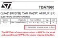
The datasheet for your TDA7396 shows a graph with 80 Whats of EIAJ fake power into 2 ohms when the power supply is boosted to 16V.
Crutchfield sells a JVC car radio for $99.99. Its total output is 200 Whats.
 

ebeowulf17

Joined Aug 12, 2014
3,307
Ok more Diptrace questions.
OK I made a couple of mistakes on plus and minus sides. I corrected them in the component editor and pattern editor. They still show up backwards in the PCB layout, What gives? Everywhere I look in the other two they are correct "now". And every time I turn around there's a "new library" when I keep placing them in the same library. And when I open that library all the components aren't there. Diptrace needs to adopt a more windows type function when I "save as" it corrects everything in that component and updates the others automatically. I still have patterns I thought I deleted and corrected showing up.
If you change a component or pattern and want the change to filter through to a schematic or pcb that uses it, you must update that component in the schematic or pcb file. I believe it's one of the many right-click options. Choosing update component should give you several options that make it easy to change just the one you clicked, or all related parts.

It works well as-is, and I'm glad changes don't automatically propagate to all old drawings. If they did, any time I tweaked a component, I'd have to figure out every pcb I'd ever used it in first, to make sure my change didn't adversely effect something in another design.
 

ebeowulf17

Joined Aug 12, 2014
3,307
Ok more Diptrace questions.
OK I made a couple of mistakes on plus and minus sides. I corrected them in the component editor and pattern editor. They still show up backwards in the PCB layout, What gives? Everywhere I look in the other two they are correct "now". And every time I turn around there's a "new library" when I keep placing them in the same library. And when I open that library all the components aren't there. Diptrace needs to adopt a more windows type function when I "save as" it corrects everything in that component and updates the others automatically. I still have patterns I thought I deleted and corrected showing up.
Don't know why you're getting lots of new libraries. The only extras I've got were all deliberate choices.

I wonder if the confusion might stem from the idea of "save as." In DipTrace component and pattern editors, any change you make is made. It's done. It happened. You already changed the part you were working on. It's too late to "save as" a new name.

If you want to make a new part based off of an old part, approach it in the opposite order. First, duplicate the original part, so you leave its original copy unchanged. Second, rename the new duplicate part however you want. Third, make changes to the part.

I'll admit this system wasn't immediately intuitive to me, but once I understood the intended workflow it turned out to be really easy and efficient.
 

Thread Starter

Berzerker

Joined Jul 29, 2018
623
Thanks ebeowulf. And I guess in a way your right I wouldn't want it to change something else in another layout that I had done. I know it's me but I've tried to stay in the same folder "this time" cos when I first started I had all kinds of folders (libraries) everywhere. it would never place them where I told it to put it, or I could see it in explorer and know it was there but when I searched it wouldn't be there. I still see "Cap Copy" everywhere I look and I still have patterns I know I deleted in explorer not Diptrace. I double checked all my components and patterns and one of the patterns show up in the PCB layout with just the ID letters that go above it "no pattern". I guess this program wants to run me through the ringer to make sure I have it right. But this holds me back from learning the silk screen part cos I have to deal with this first.
Edit: Maybe your on to something ebeowulf, I've been so use to windows "save as" and "save" function that maybe I'm missing something here. When I correct a part I hit "save as" and click that component or pattern in the pop-up window. I tried the "save" button but that's where it would never do what I wanted it to do or what I thought it should do.
 
Last edited:

ebeowulf17

Joined Aug 12, 2014
3,307
Thanks ebeowulf. And I guess in a way your right I wouldn't want it to change something else in another layout that I had done. I know it's me but I've tried to stay in the same folder "this time" cos when I first started I had all kinds of folders (libraries) everywhere. it would never place them where I told it to put it, or I could see it in explorer and know it was there but when I searched it wouldn't be there. I still see "Cap Copy" everywhere I look and I still have patterns I know I deleted in explorer not Diptrace. I double checked all my components and patterns and one of the patterns show up in the PCB layout with just the ID letters that go above it "no pattern". I guess this program wants to run me through the ringer to make sure I have it right. But this holds me back from learning the silk screen part cos I have to deal with this first.
Edit: Maybe your on to something ebeowulf, I've been so use to windows "save as" and "save" function that maybe I'm missing something here. When I correct a part I hit "save as" and click that component or pattern in the pop-up window. I tried the "save" button but that's where it would never do what I wanted it to do or what I thought it should do.
It's worth noting once again that I'm on an earlier version of the program, and it's possible they've changed behaviors, so definitely check the documentation and help files - don't take my word for anything!
 

Thread Starter

Berzerker

Joined Jul 29, 2018
623
Finally got the pattern to show up had to shut down the editor and re-open it and then reattach the pattern? Don't ask me why? It worked is all I can say. Now I have all my components, still working on the Heat sink thing. I've been trying to not ask here because I don't want everyone to think I'm just trying to just the answers I need from you all. Without someone to teach you "I just don't get the thermal resistance calculations".
I remember when I was a machinist they sent me to balancing school, it took me twice going through it to finally get it good enough to make our company an licensed dealer. Funny thing I don't remember any of it now. Old age is all I can say. I can remember having to calculate where to place the "balancing holes" to make it lighter on the heavy side but how I done it escapes me now. same with this. I have to worry about height, width and thickness aren't so much of a problem.
 

Thread Starter

Berzerker

Joined Jul 29, 2018
623
shortbus suggested:
https://www.sparkfun.com/products/9576
2.7 @ 75C
AG said:
If you power the TDA7386 from 16V then its output power will be 25W into a 4 ohm speaker then its heating will be about 20W.
The Sparkfun heatsink is rated at 2.7 degrees C rise per Watt and the chip is 1.5 degrees C/W and the joining of them is about 0.5 degrees C/W. Then the total thermal resistance is 4.7 degrees C/W and if the ambient unenclosed temperature is 30 degrees C then the maximum chip temperature will be (4.7 x 20W) + 30 degrees C= 124 degrees C so this heatsink is perfect.
OK I'm still trying to get thermal resistance
I know some of the structure of how it calculated now.
I know what theta is now, But above is throwing me off about something.
I know the junction temp needs to be 120C or lower (some say 100C is what you shoot for).
the (Jc) junction - case is 1.5 and the (Ja) ambient temp is 30C (this can vary).
But the 2.7 @ 75C is kinda throwing me off. I looked up a 1.5" length heatsink
https://www.digikey.com/product-det...ration/532602B02500G/532602B02500G-ND/1624802
Power Dissipation @ Temperature Rise 6.0W @ 40°C
Thermal Resistance @ Natural 5.50°C/W
Then I looked up a 2" length and got this:
https://www.digikey.com/product-det...ration/532702B02500G/532702B02500G-ND/1625049
Length 2.000" (50.80mm)
Power Dissipation @ Temperature Rise 10.0W @ 50°C
Thermal Resistance @ Natural 4.80°C/W

J-c+C-s+S-a = Ja. junc-case + Case-sink + sink-amb = junc-amb temp
(Ja x Pd) + Ja = Tj. junc-amb x power dissipation + temp amb = (temp) @ junction "IC"
Volts x current = Pd "power dissipation"
(Tj - Ta) / Pd = Ja. "junc amb temp"
I got this, I think?
But when you look at the two above the 2" one is 10.0 @ 50C and the 1.5" is 6.0 @ 40C. Now if I look at these numbers the longer one should in my mind have a lower power dissipation, But your looking at @75C vs @50C or @75 vs @40C. This has to matter somehow. These two are thicker than the one shortbus posted "more metal more dissipation right?"
TDA7396 datasheet:
https://www.st.com/content/ccc/reso...df/jcr:content/translations/en.CD00000164.pdf
Tcase "power dissipation" of IC = 85C or 43Watts
I don't see where AG got the 20W of heat(?) Nowhere I look do they show a formula that I can use and get this answer.
As stated the 2" is thicker material and only .500 shorter, How can they be that far apart on the numbers?.
 

Audioguru

Joined Dec 20, 2007
11,248
Looking at the datasheet of the TDA7396 again, Figure 8 shows an output into 4 ohms with 1% distortion of 22W when the supply is 14.4V and 27W with a 16V supply. Figure 13 shows heating of 12W max when the supply is 14.4V then when the supply is 16V the heating is calculated to be (27W/22W) x 12W= 14.7W. My guess of heating at 20W was wrong.
The datasheet for the 1.5" heatsink stops at 14W with a temperature rise of 68 degrees C which is too hot. The 2" heatsink shows a temperature rise of 50 degrees C with 14W or about 51 degrees with the 14.7W that will happen.
The IC has a temperature rise between the chip to its case of 1.5 degrees C per W and the joining together of the IC to the heatsink will be about 0.5 degrees C per W so the 14.7W x 2 degrees per W adds to the 51 degrees above plus an ambient of 30 degrees making the chip temperature 110.4 degrees C maximum which is hot but will not happen continuously and not often so it will be fine.
 

Thread Starter

Berzerker

Joined Jul 29, 2018
623
Thanks AG, I was racking my brain trying to figure where the 20 watts came from. No matter what I put in any formula I never came out with 20W. Found a great video on thermal heatsink calculation, the guy was slow and explained a lot but I'm still not at 100% of understanding it.
 

Audioguru

Joined Dec 20, 2007
11,248
I think the datasheet for the TDA7396 is wrong about its heating. Almost every other bridged class-AB amplifier IC shows the amount of heating when its output is almost clipping is almost the same as the amount of power output, not just half. The efficiency shown on their graph does not agree with the lines.
 
Status
Not open for further replies.
Top