Input,output impedance and impedance matching for audio amp.

kiroma

Joined Apr 30, 2014
275
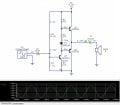
my version of the amp involved the 3 transistor configuration. The values i calculated for the components (resistors and C1) here are more trial and error based then logical calculations, I am not sure if my thinking process was right. View attachment 372242
Your input impedance (of the amplifier) is less than 200 ohms, it's too low.
You have to increase R1, R2, R3, and R4. A factor of 20 is somewhat good.
 

kiroma

Joined Apr 30, 2014
275
tried it, but increasing the factor decreased the gain at the speaker
I think that's because the higher the current the amplifier demands for the speaker, the higher the voltage drop on R4. So if you try to scale them all, you scale R4 to keep the same gain but then it prevents a higher base current on the class AB stage, thus reducing the gain. The solution to this dilemma is to have a Vbe multiplier instead of the 2 diodes. This way you can adjust the class AB stage (the output stage) collector current. The higher the current, the lower the output impedance (in this case is the resistance part).

1792070396611.png
Couldn't find a more appropriate image, but I think you can understand. R1 and R2 keep the voltages related only to the resistances. T1 makes the exponential characteristic of the Vbe multiplier.

Design Considerations
  • Current: Ensure sufficient bias current flows through the divider (typically >1mA) to keep the base current negligible compared to divider current, ensuring voltage accuracy.
  • Beta (β): Use transistors with high β to minimize base current errors.
  • Early Effect: Keeping VCE constant mitigates the Early Effect; the multiplier circuit inherently attempts to maintain a constant VCE relative to its bias point.

VCE≈VBE(1+R2/R1)
 
Last edited:

crutschow

Joined Mar 14, 2008
38,885
Are you limited to Class AB amplifiers?
A Class D switching amp could generate close to the theoretical 0.31W output into an 8Ω load from a 4.5V supply without a bridge.

If you must do a Class AB bridge amp, then you can make two identical amps, expect the input signal phase is inverted to one of the amps.
 
Last edited:

crutschow

Joined Mar 14, 2008
38,885
Thank you. This circuit seems complex based on my current understanding of audio amplifiers. If you dont mind me asking, how did you go about calculating the values for the resistors. I understand that I need to set a Q point for the transistors, but im not entirely sure on how to calculate that.
Sorry, I deleted my post before I read yours, as mine did not seem pertinent to your requirements.
That circuit was found on-line and I did not do the calculations for it.
 

Thread Starter

iLEEZi

Joined Mar 19, 2026
46
Are you limited to Class AB amplifiers?
A Class D switching amp could generate close to the theoretical 0.31W output into an 8Ω load from a 4.5V supply without a bridge.

If you must do a Class AB bridge amp, then you can make two identical amps, expect the input signal phase is inverted to one of the amps.
Yes im strictly limited to AB amplifier
 

MrChips

Joined Oct 2, 2009
35,249
I have reduced the speaker impedance from 8 Ω to 4 Ω to obtain higher output. In any case, the output cannot swing much more than 1-2 V peak to peak.

Let's say that the speaker is driven at 2 V. It needs a current of 500 mA.
Assume the current gain of the transistor is 100. We need a base current of 500 mA / 100 = 5 mA.
If we drive the base of Q1 with 5mA @ 2V, R1 = (4.5 V - 2 V) / 5 mA = 500 Ω

2-diode drop gives a reasonable constant voltage between the base of the output transistors.
Replacing one of the diodes with a resistor allows you to adjust this voltage and hence allows you to tolerate slightly more cross-over distortion. R2 is adjusted to allow a small amount of cross-over distortion. This reduces the idle current through Q1 and Q2.

R3 is added to provide some negative feedback for Q3.

Select R4 and R5 for similar reasons, i.e. start with the collector current, calculate the required base current, and adjust R4/R5 ratio for proper voltage Vcc/2 at the output.
 

crutschow

Joined Mar 14, 2008
38,885
MrChips made a good point.
If you lower the speaker impedance the amp sees (either with a lower impedance speaker, or two or more speakers in parallel) you could conceivable get your desired 0.3W output without going to a bridge amp.
Is that acceptable?
 
Thank you. This circuit seems complex based on my current understanding of audio amplifiers. If you dont mind me asking, how did you go about calculating the values for the resistors. I understand that I need to set a Q point for the transistors, but im not entirely sure on how to calculate that.
Certainly amplifier circuits become more complex as the requireent for lower distortion becomes more important! That is because of various non-linearities of most components. Amplifier distortion versus complexity and cost has been a concern since the first amplifier circuit..
If you take a look at any of the low-distortion amplifiers marketed or published, that can be easily verified.
 
Last edited:

kiroma

Joined Apr 30, 2014
275
2-diode drop gives a reasonable constant voltage between the base of the output transistors.
Replacing one of the diodes with a resistor allows you to adjust this voltage and hence allows you to tolerate slightly more cross-over distortion.
So you decrease the crossover distortion to increase the distortion (I meant decreasing linearity) through the whole range?
I don't think it's a good choice. A Vbe multiplier is better as you can adjust it finely and also it doesn't vary that much with current, as a 100 ohm resistor would.
 

Thread Starter

iLEEZi

Joined Mar 19, 2026
46
I have reduced the speaker impedance from 8 Ω to 4 Ω to obtain higher output. In any case, the output cannot swing much more than 1-2 V peak to peak.

Let's say that the speaker is driven at 2 V. It needs a current of 500 mA.
Assume the current gain of the transistor is 100. We need a base current of 500 mA / 100 = 5 mA.
If we drive the base of Q1 with 5mA @ 2V, R1 = (4.5 V - 2 V) / 5 mA = 500 Ω

2-diode drop gives a reasonable constant voltage between the base of the output transistors.
Replacing one of the diodes with a resistor allows you to adjust this voltage and hence allows you to tolerate slightly more cross-over distortion. R2 is adjusted to allow a small amount of cross-over distortion. This reduces the idle current through Q1 and Q2.

R3 is added to provide some negative feedback for Q3.

Select R4 and R5 for similar reasons, i.e. start with the collector current, calculate the required base current, and adjust R4/R5 ratio for proper voltage Vcc/2 at the output.
1792088479534.pngthese are the resistor values I calculated which do amplify the signal but I am doubtful because the values are too small.
 

Thread Starter

iLEEZi

Joined Mar 19, 2026
46
MrChips made a good point.
If you lower the speaker impedance the amp sees (either with a lower impedance speaker, or two or more speakers in parallel) you could conceivable get your desired 0.3W output without going to a bridge amp.
Is that acceptable?
that would be acceptable, but implementing the bridge would reward more marks. And it seems like an interesting concept I can further learn about.
 

Thread Starter

iLEEZi

Joined Mar 19, 2026
46
Certainly amplifier circuits become more complex as the requireent for lower distortion becomes more important! That is because of various non-linearities of most components. Amplifier distortion versus complexity and cost has been a concern since the first amplifier circuit..
If you take a look at any of the low-distortion amplifiers marketed or published, that can be easily verified.
I would consider designing a low distortion circuit, but it seems like I am unable to fully understand the basic circuits.
 

MrChips

Joined Oct 2, 2009
35,249
As already pointed out, you are already working at a disadvantage by operating at such a low supply voltage. So everything at this point becomes a compromise, which includes distortion.

Automotive audio amplifiers take the 12 V battery voltage and converts it to 40 to 100 V in order to deliver power.

For best efficiency at low voltages, you need a Class-D amplifier.
 

crutschow

Joined Mar 14, 2008
38,885
Automotive audio amplifiers take the 12 V battery voltage and converts it to 40 to 100 V in order to deliver power.
Where did you find that info?
I think auto audio amplifiers are Class-D bridged which can deliver over 20W into a 4Ω speaker from the 14V when the engine is running, and autos typically have several amplifier/speakers per channel.
 
Last edited:
Where did you find that info?
I think auto audio amplifiers are Class-D bridged which can deliver about over 20W into a 4Ω speaker from the 14V when the engine is running, and autos typically have several amplifier/speakers per channel.
I have opened and investigated a couple of HIGHER POWERED (more than 30 watts) auto style amplifiers AND CERTAINLY they DO INCLUDE VOLTAGE BOOSTING!!
MrC is totally correct!!
The reasoning for operation at the higher voltages are several, but the simplest part is that high power at low voltage demands high current, and that gets incredibly difficult ar 12 volts. Aside from being difficult, it would also require impedance matching transformers that are BIG, and HEAVY, and EXPENSIVE.

Look at the circuit for any good quality sound system and the voltages are a lot higher than 12 volts, often closer to 100 volts, always above 50 volts. (or +/- 45 volts for a few 1965 systems.)
 
Top