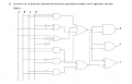
All of the unnecessary wire crossings and jogs. How pitiful. And using humps instead of connection dots. Thankfully that style went out many decades ago.
All of the unnecessary wire crossings and jogs. How pitiful. And using humps instead of connection dots. Thankfully that style went out many decades ago.
Yes, I can do it with one hand tied behind my back. Do you know the function of each gate from the symbols? If not, you should start there. Once all the symbols are tagged with an identifier. We can name them and help you decode the function of each gate.
So show your best effort to get as far as you can. We can then help you go a bit further, or explain why what you have done thus far has a mistake. We won't just do your homework for you.
Don't give up yet. The wire crossings are annoying but they won't change the logic functions.
Start from the upper left had corner and write out the logic function for the first gate. I'll help you start but you really have to do most of the work yourself, or at least try.
First it is a good idea to label all of the outputs of every gate and inverter. Call them a1, a2, a3, or g1, g2, g3, etc. That allows you to build up the complete expression.
The first gate is a 3 input AND gate and we can call the output g1. With AND gates we usually use what seems like multiplication to show the output. With inputs coming from B, C, and D, that means we might write:
g1=B*C*D
and sometimes we can get away with just g1=BCD but it is probably better to keep the multiplication symbols for now because when you get to inverters you have to add a notation like B' or C' or D', unless you can stand to look at notations like B'C'D and not miss anything.
So the output of that first gate, using this notation, is:
g1=B*C*D
If we move down the page a little we get to the first inverter. The only input is D and we can call the output g2. That means we can write:
g2=D'
using the apostrophe for inversion. In more formal writing they use a line over the top of the symbol, so you would see a line over the D.
You'll note that the output of that inverter connects to an exclusive or gate. The inputs are g2 and A. We can call the output g3 and write g3=Axg2' where 'x' means exclusive OR (or XOR). Since we know that g2=D' we can also write out:
g3=AxD'
Later, you will want to look up the expanded expression for the exclusive OR function so you can write it out in terms of either AND, NAND, OR, NOR, or INV (invert), and that will require some combination of those.
Going down to the lowest AND gate it's a little simpler. We just have inputs that are C' and B. C' came from inverting C. The output of that gate (calling that g4) is just:
g4=B*C'
Doing this for all the gates we end up with a possible large expression, which we then use various logic rules to reduce. You'll have to look into how to do that or ask more questions right here.
Do you seek the circuit's truth table or do you seek the Boolean equation that expresses each output in terms of the inputs, these are different questions and it's not clear which one you are asking, but it seems it is the latter, you want the Boolean expressions - is that true?

 Facebook
 Google
 GitHub
 Linkedin
 36.9 KB Views: 27





