How to trigger a relay based on a resistance drop in a Push to Start Switch

Thread Starter

Restomod

Joined Jan 17, 2026
70
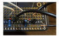
While I made two more not soldered, careful not to have shorts, sometimes the pins didn’t connect well

so I soldered this one and measured V step by step

L78L05 on board 5v constant, not getting hot etc

Next step
Switch on


NO 3.5v
Closed 1.9

next step LM393

12v in
GND
12k and 10k
crossovers 2 to 6, 3 to 5

this is where I see fluctuation

7 open varies .7,.5 then .3,.2
7 closed when at .3 open 1.3v, 1.2v when at .2

1 open mostly fluctuating .2,.3
Closed .98, .99

So on this one there is a 1v increase

Why the others did not respond not sure the LM393 is a TI chip
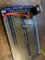
IMG_6382.jpegimage.jpg
 

sghioto

Joined Dec 31, 2017
8,737
Try this:
Remove the transistor base connections from the circuit board and shown below.
Read the voltages on all pins of the LM393 with switch Open and Closed.
1770502150840.png
1770502405478.png
 
Last edited:

Thread Starter

Restomod

Joined Jan 17, 2026
70
What you’re asking is basically the board I posted this morning…?

The board in the last pic I posted, no transistors - these are the values on the LM393

8 13vi
4 gnd
7 o 0v
7 c .78v
6 o 3.5v
6 c 1.89v
5 o 2.282
5 c 2.281
3 same as 5 - should be note 3rd decimal
2 o 3.5v
2 c 1.89v
1 o 0v
1 c .8v

1 & 7 when switch closed show fluctuation, a second pass at the measuements .89v
 

Thread Starter

Restomod

Joined Jan 17, 2026
70
So this above is before adding the 1k ohm resistors

with pin 1 & 7 tied to 1kohm their valuse are the same:

open .200v
closed 5v

no change in pins 2,3,5,6
 

sghioto

Joined Dec 31, 2017
8,737
The LM393 circuit is working correctly.
Now, need to make sure the transistors are not defective and installed correctly.
What transistor part no. are you using ?
 

Thread Starter

Restomod

Joined Jan 17, 2026
70
2N3904

According to the spec sheet

1 GND
2 input
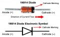
3 output to relay & the diode - is the diode on the shematic correctly according to the spec attached?1N914 diode pinout.jpg

2N3904 npn.jpg
 

Thread Starter

Restomod

Joined Jan 17, 2026
70
quick update - when I was doing this a weekago, three of the amzn sourced 78L05 got hot nearly instantly, I'm waiting for TI Texas Inst sourced ones to arrive. later thsi week
 

Thread Starter

Restomod

Joined Jan 17, 2026
70
Okay
All soldered up

both relays latch on pushing the button

Big question

which of the two relays is Ignition On

and which is the starter?

More … what should the voltage be on the open wire on the relay?
 

panic mode

Joined Oct 10, 2011
5,153
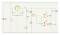
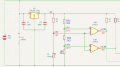
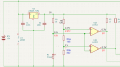
there are two comparators. in roder to compare things, each of them ha two inputs marked + and -.
on first comparator, input "+" is on pin3 and input "-" is on pin2.
if voltage at "+" is greater, output (pin1) will go high.
if voltage at "-" is greater, output (pin1) will go low.
U2 provides stable 5V which is then used to create two voltage dividers.
in this case lets focus on first one, which is made of R1 and R2.
since R1 is on low side (this is your trigger), if it is disconnected, there is nothing to pull input "-" low. but R1 is still present and it will pull that input high (to 5V).
since voltage ar the input "-" (pin2 = 5V) is greater than voltage at input "+" (pin3 = 2.27V), output 1 will go low (down to 0.3V or less).

but since both comparators (U1A and U1B) have inputs wired in parallel, both will see same voltages and both will react the same way.
if the goal is to have two distinct trip points (press a little and first relay is on, press harder both relays are on), you would need to separate the reference inputs (in this case pins 3 and 5 are looking at same fixed reference of 2.27V)so that they can be set to different levels - as shown at the very begin of this thread. that is why i suggested using trimmer potentiometers. yo can simply use one hand to press the trigger and use another to adjust trimmer till corresponding relay switches on. then you do the same with the second trimmer.

if you want to use fixed resistors like R5 and R6, you would need to know what resistance values of the trigger are needed for each press. then one can calculate needed voltages.
if you want to try it without calculating, replace R5 (12k) with two resistors. for example the top side could be R5a=10k and the bottom side would be R5b=2k2 or R5b=1.8k. this way total resistance of R5a+R5b is about the same (12k) but the new midpoint between those two resistors can be used as a separate threshold (slightly different reference for one of the comparators). so then simply move pin 3 ("+" input of U1A) from the bottom side of the R5b to the top side of R5b. so U1A will some 2.7V as threshold while U1B will still see about 2.27V.

or... you can keep R5 as is, and just add new resistor between R5 and R6 such as 1-3k (it need to be small compared to R5 and R6, maybe 1/10 or so of their value).
as long as threshold voltage is different you can have circuit to produce two distinct outputs based on applied pressure on the trigger button.

1771636803640.png
 

panic mode

Joined Oct 10, 2011
5,153
actually, if pressing start button reduces resistance, you would probably want to split the bottom resistor.
that meals keep R5 as is and change R6 into something like 1.5 or 1k8 on top, and 8k2 on the bottom.
1771637430037.png
 

Thread Starter

Restomod

Joined Jan 17, 2026
70
Okay to continue the diagnosis

I want to go back to my questions

what should the relays measure as out put when latched?

12v is what it should be

with audible and physical latching, why would it not be 12v?
 
Last edited:

panic mode

Joined Oct 10, 2011
5,153
it depends how you measure. if relays turn on and off, clearly they are working.

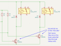
as common, they are driven by switching low side. so if you keep black DMM probe on negative rail (aka GND, aka 0VDC) and probe voltages at different points using red DMM probe, you will see that output voltage is near zero when relay is on, and 12V when relay is off. it looks backwards because relay driver is controlling low side of the coil. it is possible to use high side switch too and then you would see 0V when relay is off, and 12V when relay is on but circuit would have more parts.

the other way to do this, is to measure voltage directly across relay coil. if using this to check for voltage across relay coil, it does not matter if driving transistor is on low or high side : black probe on one side of relay coil, the red probe on the other side of the relay coil. if you see negative value, swap the probes. when you see 0V, relay is not energized (it is off), when it is energized you will see 12V.

1771642308102.png
 

sghioto

Joined Dec 31, 2017
8,737
Okay
All soldered up
both relays latch on pushing the button
That's nice you finally have the original circuit working.
However the relays only stay ON while the button is pressed which is not what you requested earlier in the thread.
My version of the circuit required is back in post #42.
 

Thread Starter

Restomod

Joined Jan 17, 2026
70
That's nice you finally have the original circuit working.
However the relays only stay ON while the button is pressed which is not what you requested earlier in the thread.
My version of the circuit required is back in post #42.

Okay - I see that and I'll make that one as replication of the exact automotive push start is what is needed.

Nowm using the circuit in post #42 the switch 1 has 1.55k and 1k open closed value.

Does anything need to change in the circuit when we use the actual switch having 2.39ohm and 0,60ohm values, open/closed?
 

sghioto

Joined Dec 31, 2017
8,737
Does anything need to change in the circuit when we use the actual switch having 2.39ohm and 0,60ohm values, open/closed?
No. Keep that part the same as it is working correctly.
In that schematic (#42), K1 is the starter relay.
 
Last edited:

Thread Starter

Restomod

Joined Jan 17, 2026
70
No. Keep that part the same as it is working correctly.
In that schematic (#42), K1 is the starter relay.
The intended use - out of the relay 12v signal - use invert-mini turns this into a ground signal and turns on both the ignition circuit and the starter - as long as the button is held.

Letting off the button leaves the ignition on circuit live, vehicle running until the button is pushed again.

The canbus system referenced is made by infinitybox, 2022 version, not Next Gen. There isn't a lot of info out there on how their side works, however >

Point is this one button push start works with a variety of visually boring push start switches, among then Honda & Nissan.

So as I await arrival today of the fullsize pcb and the resistors I ran short on, with the schematic in #42, I think we need the older style function on the IB system that has a separate wire for Starter and Separate wire for Ignition.

If we have one signal wire that does both on the IB side, the second relay isn't connected to anything...

Thoughts?
 
Top