Facebook
 Google
 GitHub
 Linkedin
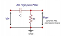
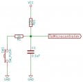
I am trying to build a hardware debounce circuit after Elliot Williams published here. This is his schematic:
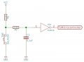
Elliot shows this behaviour:
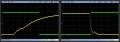
The right hand trace shows the voltage at the output of the RC stage (yellow) and the trigger (green) when the switch closes, the left hand when it opens again.
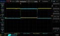
What I get is this
Switch closing:
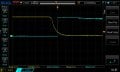
Yellow after RC, blue trigger output. So far so good, but zooming out to see the whole button press:
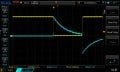
Can anyone suggest a reason for this behaviour? I don't understand (a) why the Schmitt trigger doesn't latch to +5V for the duration of the button press and (b) how it swings to -5V (ish) when the button is released.
I'm probably being thick (very new to playing with electronics), any education would be most welcome.
Bob.
Elliot shows this behaviour:
The right hand trace shows the voltage at the output of the RC stage (yellow) and the trigger (green) when the switch closes, the left hand when it opens again.
What I get is this
Switch closing:
Yellow after RC, blue trigger output. So far so good, but zooming out to see the whole button press:
Can anyone suggest a reason for this behaviour? I don't understand (a) why the Schmitt trigger doesn't latch to +5V for the duration of the button press and (b) how it swings to -5V (ish) when the button is released.
I'm probably being thick (very new to playing with electronics), any education would be most welcome.
Bob.
Attachments
-
 18.8 KB Views: 3